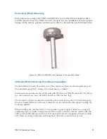
Lightning Arrestors
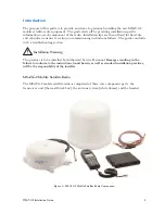
The applicable electrical code(s) may require that lightning arrestors capable of supporting L-
band transmissions be installed on all cabling between the fixed-site antenna and the structure
which the equipment is housed in. It is also suggested that any structure containing the radio
be equipped with a lightning rod connected to the ground. The professional doing the fixed-
site installation is responsible for determining all such requirements with the customer and
installing the equipment such that it complies with all applicable standards.
Installing the TU – Fixed-site and Vehicle
Installation – General
1) For ease of service, route the radio cables and power cables together.
2) Always disconnect the negative side of the vehicle battery prior to any electrical work.
3) Whenever routing cable through holes drilled in metal or through bulkheads, use
grommets and RTV sealant to weatherproof all holes drilled on the outside of the
vehicle.
4) Use cable ties every 30 – 45 cm (12-18”).
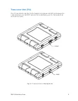
5) The TU can be mounted in either the horizontal or vertical position.
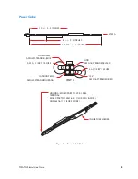
6) The main power line should be connected directly to the vehicle battery (or 12 VDC
power supply). If you must connect it to another circuit, ensure sufficient amperage
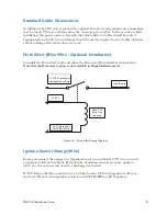
is available. In the case of a fixed-site installation, tie the Battery and Ignition Sense
wires together on the 12 VDC power source.
7) The ground line should be connected directly to the vehicle’s battery ground.
8) Install the TU in a protected but ventilated area (inside building or vehicle). Allow
at least a one (1) inch space around all surfaces, except for the surface attached to
the mounting bracket to provide adequate cooling. Ensure that the location is
accessible for servicing.
9) The TU is not waterproof.
10) Always provision the wiring into the TU with a drip loop.
11) With the exception of the TU to Antenna cable, do not route the cables outside
the vehicle.
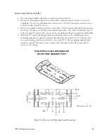
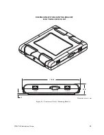
Mounting Bracket Information
NOTE: Use care when drilling through the body of the vehicle to avoid puncturing critical
items.
The bracket is connected to the TU with two (2) provided screws. There is a 5mm gap
between the TU and the bracket.
MSAT-G2 Installation Guide
11
Summary of Contents for MSAT-G2
Page 1: ......


