background image

MTM800 FuG/

MTM800 FuG ET

Installation Manual

Installationshandbuch

*68015000553*

68015000553-KC

Januar 

2017

©

 2017 Motorola Solutions, Inc. All rights reserved

Summary of Contents for MTM800 FuG ET

Page 1: ...MTM800 FuG MTM800 FuG ET Installation Manual Installationshandbuch 68015000553 68015000553 KC Januar 2017 2017 Motorola Solutions Inc All rights reserved ...

Page 2: ......

Page 3: ... law in the sale of a product Disclaimer Please note that certain features facilities and capabilities described in this document may not be applicable to or licensed for use on a particular system or may be dependent upon the characteristics of a particular mobile subscriber unit or configuration of certain parameters Please refer to your Motorola Solutions contact for further information Tradema...

Page 4: ...This page intentionally left blank ...

Page 5: ...ower Cables 39 3 4 Installing Ignition Sense Cable 39 3 4 1 Ignition Sense Cables 40 Chapter 4 Radio Installation 41 4 1 Dashboard Installation 41 4 1 1 Installing the Radio in an Automotive Dashboard 41 4 1 2 Mounting the Radio in the Frame 41 4 1 3 Removing the Radio from the Frame 42 4 2 Desktop Installation 43 4 2 1 Desktop Installation Planning 43 4 2 2 Desktop Installation 43 4 3 MTM800FuG R...

Page 6: ...ount Enhanced Control Head 74 4 6 Data Expansion Head Enhanced Installation 74 4 6 1 Data Expansion Head Enhanced Radio without Control Head 74 4 6 2 Data Box Radio 74 4 6 3 Data Expansion Head Enhanced with Third Party Control Head 75 4 6 4 Junction Box Installation 76 4 6 5 Installing Junction Box 78 4 6 6 Connecting Accessories to the Junction Box 78 4 6 7 Connectors on the Junction Box 79 4 6 ...

Page 7: ...tyle Control Head Y Cable Accessories Expansion Cable 111 5 9 8 Radio to Junction Box 112 5 9 9 Data Expansion Head Enhanced Radio to Data Device 114 5 9 10 Data Expansion Head Enhanced Radio to Fist Microphone 114 5 9 10 1 Removing the Existing Coiled Cord Cable 115 5 9 11 Radio to Data Device Active Data Cable 116 Chapter 6 External Equipment Installation 117 6 1 Vehicle Antenna Installation 117...

Page 8: ...This page intentionally left blank ...

Page 9: ... 16 Dual Control Head with a Combination of eCH and TSCH 53 Figure 17 Multi Radio Control Installation with eCH 54 Figure 18 Multi Radio Control Installation with TSCH 54 Figure 19 Ethernet Cable PMKN4141_ PMKN4140_ PMKN4139_ PMKN4138_ PMKN4136_ and PMKN4146_ 55 Figure 20 Ethernet Cable PMKN4135_ 55 Figure 21 Ethernet Cable PMKN4176_ PMKN4177_ and PMKN4178_ 56 Figure 22 Remote Mount Enhanced Contr...

Page 10: ... Mounting 88 Figure 53 Location of Accessory Connector Rear Side 89 Figure 54 Accessory Connector 91 Figure 55 26 Pin Accessory Connector 92 Figure 56 Connecting Diagrams 92 Figure 57 Data Expansion Head Enhanced Front View and Connector Location 93 Figure 58 Remote Head Enhanced Front View and Connector Location 94 Figure 59 Ethernet Expansion Head Enhanced Front View and Connector Location 97 Fi...

Page 11: ...andardized RS232 Cable 114 Figure 76 Pin Assignment of Cable from Accessory Connector to Microphone Housing 115 Figure 77 Active Data Cable PMKN4104_ 116 Figure 78 Connections to the Rear Side of the Radio 118 Figure 79 External Speaker Trunnion Bracket 120 68015000553 KC List of Figures Send Feedback 11 ...

Page 12: ...This page intentionally left blank ...

Page 13: ... Box Mount 26 Table 15 Power Supplies 26 Table 16 Power Cables 26 Table 17 Cables 26 Table 18 Junction Box 27 Table 19 Power Cables to Mobile Terminal 27 Table 20 Installation 27 Table 21 Mounting Transceiver 27 Table 22 Mounting Control Head 28 Table 23 Programming Data 28 Table 24 Antennas 28 Table 25 GPS 28 Table 26 Control Heads 29 Table 27 Microphones 29 Table 28 Loudspeakers 30 Table 29 Hand...

Page 14: ...nnector of the Enhanced Control Head 100 Table 57 10 Pin Telco Connector 102 Table 58 25 Pin Back Connector 102 Table 59 Mobile Microphone Port Connector 104 Table 60 10 Pin Ethernet Connector 105 Table 61 25 Pin Back Connector 105 Table 62 Accessories Expansion Cable Connections 108 Table 63 Pin Assignment of the 10 Pin Audio Connector Telephone Style Control Head 109 Table 64 Pin Assignment of t...

Page 15: ...Table 73 Fuse Identification 131 68015000553 KC List of Tables Send Feedback 15 ...

Page 16: ...This page intentionally left blank ...

Page 17: ...oderate injury or serious product damage CAUTION The signal word CAUTION may be used without the safety icon to state potential damage or injury that is not related to the product IMPORTANT IMPORTANT statements contain information that is crucial to the discussion at hand but is not CAUTION or WARNING There is no warning level associated with the IMPORTANT statement NOTICE NOTICE contains informat...

Page 18: ...This page intentionally left blank ...

Page 19: ...t Safety Guide For Two Way Radios IMPORTANT Before using this product read the RF Energy Exposure and Safety Guide shipped with your radio The guide contains recommendations for safe usage important RF energy awareness and control information as well as regulatory information to help ensure compliance with applicable standards and regulations 1 2 MTM800 FuG MTM800 FuG ET Manuals and User Guides Pr...

Page 20: ...Safety Leaflets 6866537D37 Mobile Safety Leaflet EMEA 68015000553 KC Chapter 1 Scope of This Manual 20 Send Feedback ...

Page 21: ...phone or Handset Remote Mount cables Standard User Guide and Installation Accessories M4 Motorcycle Mount with Mobile Terminal with Motorcycle Mount Enhanced Control Head optional either with Remote Head Enhanced or Data Expansion Head Enhanced Speak er Microphone or Handset Motorcycle cables Standard User Guide and Installation Ac cessories Dual Control Mount with two Enhanced Control Heads maste...

Page 22: ...imary Operation N Standard Package G FuG Models 2 3 Mobile Terminal Model Information NOTICE Motorola Solutions uses sales model prefixes to denote regional kit differences AZ or MD may be found in use Table 4 Type and Model Numbers This manual applies to the following Mobile Terminal Models Type No Sales Model No Short Description Model MT953CG M83PFS6TZ5AG MTM800 FuG 380 430 MHz DASH M1 M83PFS6T...

Page 23: ...s HxWxD in mm Transceiver with Enhanced Control Head Dash Mount MTM800 FuG 60 x 188 x 198 Dimensions HxWxD in mm Transceiver with Ethernet Expansion Head MTM800 FuG ET 45 x 170 x 190 Ethernet Control Head eCH 60 x 190 x 40 Telephone Style Control Head TSCH 220 x 65 x 75 Weight in grams Transceiver with Enhanced Control Head Dash Mount MTM800 FuG 1500 Weight in grams Transceiver with Ethernet Expan...

Page 24: ...er Value Modulation Type µ 4DQPSK RF Power TMO Adjustable to Class 2 10 W Class 2L 5 6 W Class 3 3 W Power in MSPD mode limited to Class 2L Power in TEDS mode limited to Class 3 DMO Adjustable to Class 2 10 W Class 2L 5 6 W Class 3 3 W Power in MSPD mode limited to Class 2L Power in TEDS mode limited to Class 3 Frequency Range TMO MT953CG 380 430 MHz Frequency Range DMO MT953CG 380 430 MHz Frequen...

Page 25: ...hone PMMN4070_ x x x x x Compact Fist Microphone with a clip RMN5107_ x x x x Desktop Microphone Mobile Microphone Port RMN5106_ x x x Fist Microphone with a clip2 GMMN4063_ x x x x Hearer Speaker Microphone with Earphone Jack and Emergency Button PMMN4086_ x x x x x Heavy Duty Fist Microphone RMN5111_ x x x x x Push Button PTT for use with RMN5054_ or PMMN4087_ RLN5926_ x x x x x Smart Visor Micr...

Page 26: ...ssory Part Number M1 M2 M3 M4 M5 Desktop Tray with Loudspeaker RSN4005_ x Desktop Tray without Loudspeaker GLN7318_ x Table 15 Power Supplies Accessory Part Number M1 M2 M3 M4 M5 Desktop Power Supply HPN4007_ x x Power Supply PMPN4055_ x x Wedge Power Supply PMPN4076_ x x Table 16 Power Cables Accessory Part Number M1 M2 M3 M4 M5 Cable Assembly for use with PMPN4055_ or PMPN4076_ PMKN4165_ x x Eur...

Page 27: ... Power Cables to Mobile Terminal Accessory Part Number M1 M2 M3 M4 M5 12 V Power Cable to Battery 3 m with Fuse 10 A GKN6270_ x x x 12 V Power Cable to Battery 6 m with Fuse 10 A GKN6274_ x x x Table 20 Installation Accessory Part Number M1 M2 M3 M4 M5 Accessory Connector Kit junction box 26 pin plug1 PMLN5072_ x x x x Accessory Connector Kit radio rear use with a Junc tion Box HLN9457_ x x x x Ex...

Page 28: ...0 MHz GMAE4282_ x x x x x GPS TETRA COMBI Antenna Kit 380 430 MHz GMAE4248_ x x x x x Antenna Whip Tetra Hinged 380 430 MHz GMAE4253_ x x x x x Antenna Tetra Panel Roof Mount 380 430 MHz GMAE4255_ x x x x x Antenna Whip Tetra Flexible Hinged 380 430 MHz GMAE4281_ x x x x x Antenna Whip Tetra Hinged 380 430 MHz GMAE4284_ x x x x x Antenna Mount Magnetic GMAE4279_ x x x x x Antenna Mount Panel Roof ...

Page 29: ...044003 Toroid Part Number 01015001001 2 6 MTM800FuG ET Accessories to Model Chart NOTICE Contact your service provider for further information on additional and specialized accessories supported by MTM800 FuG ET Table 26 Control Heads Accessory Part Number M1 M2 M3 M4 M5 Ethernet Data Expansion Control Head PMLN7009_ x Ethernet Remote Control Head eCH Roman PMWN4024_ x Ethernet Telephone Style Con...

Page 30: ...umber M1 M2 M3 M4 M5 External PTT with Emergency Footswitch2 RLN4836AR x x x x x Gooseneck PTT2 RLN4858_ x x x x x Pushbutton PTT2 RLN5926_ x x x x x Pushbutton with Remote PTT2 RLN4857_ x x x x x Table 31 Cables Accessory Part Number M1 M2 M3 M4 M5 Accessory Kit PMLN6487_ x RECH Y Cable with Fuse 2 A PMKN4133_ x SIM Card Reader Cable 60 cm PMKN4137_ x SIM Card Reader Cable 195 cm PMKN4142_ x TETR...

Page 31: ...091_ x x x x Table 34 Mounting Transceiver Accessory Part Number M1 M2 M3 M4 M5 High Profile Mounting Bracket GLN7317_ x x x x x Key Lock Mount RLN4779_ x x x x x Low Profile Mounting Bracket GLN7324_ x x x x x Mounting Frame to Install Transceiver in DIN A Slot PMLN5094_ x x x x x Table 35 Mounting Control Head Accessory Part Number M1 M2 M3 M4 M5 DIN Mount Bracket PMLN5093_ x Motorcycle Mount Tr...

Page 32: ... x x x x x Antenna Whip TETRA Hinged 380 430 MHz GMAE4284_ x x x x x Antenna Mount Panel Roof thickness up to 4 mm GMLN4276_ x x x x x Antenna Mount Panel Roof thickness up to 6 mm GMLN4277_ x x x x x Antenna Mount Magnetic GMLN4278_ x x x x x Table 38 GPS Accessory Part Number M1 M2 M3 M4 M5 Antenna Comb Tetra GPS 380 430 MHz SMA GMAE4507_ x x x x x Antenna GPS Only Magnetic Mount SMA GMAG4254_ x...

Page 33: ...nhanced and the Active Data Cable PMKN4104_ cannot be used 4 Use both for programming and data purposes CAUTION Complex installations requiring extended cable runs and Remote Mount Control Heads with Audio Accessories such as the Telephone Style Handset HLN7016_ may benefit from careful routing of cables and in some cases additional Electro Magnetic Compatibility EMC reduction techniques such as u...

Page 34: ...This page intentionally left blank ...

Page 35: ... required Use only DC DC converter vendors who provide a certification for vehicle installation and meet radio Power Supply specification Motorola Solutions recommends a suitable range of DC DC converters available from Alfatronix LTD UK Some models are also available through Motorola Solutions Service Organization check with your Account Manager Be aware when planning the installation that there ...

Page 36: ...bove the catalytic converter b Make sure that the power cable never rests on sharp edges c Use grommets whenever a cable has to pass through a hole in a metal panel CAUTION Improper handling with the power cable may cause shorting to ground Ensure that during radio installation the power cable fuse is removed Make sure that your power cable is not placed with the antenna in parallel Interference c...

Page 37: ...sing the provided ring lug if necessary Shorten the black lead to remove any excess cable NOTICE Locate a good vehicle ground point The vehicle frame provides the best ground Optimum radio performance can only be achieved with a low resistance ground connection Verify that the connections between the battery negative terminal vehicle chassis and engine block have low resistance 68015000553 KC Chap...

Page 38: ...ng its mounting hole and dress the wires as required 6 Insert the stripped end of the red lead of the fuse holder into the ring lug hole and crimp it Connect the fuse holder red adapter lead plug to the mating receptacle on the red lead of the power cable 7 Connect the red lead ring lug from the fuse holder to the positive battery terminal Make sure that the adapter cable is connected to the main ...

Page 39: ...g Ignition Sense Cable The Ignition Sense Cable allows the radio to be turned on and off by the vehicle ignition switch 3 4 Installing Ignition Sense Cable The PMKN4120_ Ignition Sense Cable allows the terminal to be turned on and off by the vehicle ignition switch CAUTION In cases of blown fuses replace only with fuses of identical value Never insert ones of different values Ensure that the fuse ...

Page 40: ...Motorola Solutions recommends a suitable range of DC DC converters available from Alfatronix LTD UK Some models are also available through Motorola Solutions Service Organization check with your Account Manager The ignition sense cable kit contains a thin cable and a fuse holder 3 4 1 Ignition Sense Cables Table 42 Ignition Sense Cables Number Description Rating PMKN4120_ Ignition Sense Cable with...

Page 41: ...top and rear of the frame should also be secured with screws The demount tool can be used as an aid to mounting as well as demounting 4 1 2 Mounting the Radio in the Frame Procedure 1 Provide the electrical connections to the radio for power antenna and accessories 2 Plug in all the connectors and push the radio with its Remote Head Enhanced or alternatively the Data Expansion Head Enhanced firmly...

Page 42: ...094_ includes Demount Tool 4 1 3 Removing the Radio from the Frame Procedure 1 Remove both rubber side caps from the Enhanced Control Head 2 Insert the demount tool into the two openings 3 Push the demount tools through the openings in the frame 4 Slide out the radio 68015000553 KC Chapter 4 Radio Installation 42 Send Feedback ...

Page 43: ...lation Before a hole is drilled or a wire is run inspect the location and determine how and where you intend to mount the antenna terminal and accessories Plan wire and cable runs to provide maximum protection from pinching crushing and overheating Only competent personnel able to ensure that the complete installation fulfils its regulatory requirements such as EMC Electro Magnetic Compatibility a...

Page 44: ...C C C C C C C C C C C C C C C C C C C C CCCCC C C C C C C C C C C C C C C CCCCC 1 2 3 4 5 7 8 9 10 12 6 11 Number Description Part Number 1 Desk Microphone RMN5106_ 2 Loudspeaker RSN4002_ RSN4003_ or RSN4004_ 3 DC Power Cable GKN6266_ or PMKN4165_ for use with PMPN4055_ or PMPN4076_ 4 Power Supply GPN6145_ HPN4007_ PMPN4055_ or PMPN4076_ 5 Line Cord with Ground 6 Wall Outlet 7 Desktray or Desktray...

Page 45: ...bile GKN6266_ 9 Cable Assembly for use with PMPN4055_ and PMPN4076_ PMKN4165_ 10 Lightning Protector with Quarter Wave Stub Protector in the appropriate frequency range 4 3 MTM800FuG Remote Mount Installation There are two types of remote mount installations Remote Mount Installation with standard Expansion Head PMLN4904_ Remote Mount Installation with Data Expansion Head PMLN4908_ Figure 7 Remote...

Page 46: ...on Kit Wind the Remote Mount Cable ten times around each toroid Place each toroid 30 0 2 5 cm respectively from the expansion head and the control head Winding at both ends reduces the effective cable length approximately by 0 8 m Fix the toroids firmly to a stable surface once the Remote Mount Cable is connected 4 3 1 Installing the Remote Mount Enhanced Control Head onto the Remote Mount Trunnio...

Page 47: ...anced Control Head in a DIN Mount Bracket When and where to use Follow these steps to install the Remote Mount Enhanced Control Head in a DIN Mount Bracket Procedure 1 Slide the Remote Mount Enhanced Control Head onto the DIN Mount Bracket until it snaps into place 2 Tighten the screws at both sides of the DIN Mount Bracket 68015000553 KC Chapter 4 Radio Installation Send Feedback 47 ...

Page 48: ...h the DIN mount bracket Procedure 1 Insert the mounting frame into the DIN Mount Bracket and retain it by bending back the relevant fixing tabs 2 Use all six tabs if necessary to hold it in place NOTICE The tabs are easily bent back by twisting a large flat bladed screwdriver into the slot behind the tabs For a more secure installation the top and rear of the frame should also be secured with scre...

Page 49: ...it 4 3 4 Adding Extra Accessories to the Remote Head by Expansion Cable The Accessories Expansion Cable PMKN4029_ allows the radio to have extra accessories using the Mobile Microphone Port MMP 68015000553 KC Chapter 4 Radio Installation Send Feedback 49 ...

Page 50: ...ws at the subD connector 3 The Mobile Microphone Port MMP USB port module can be mounted to various surfaces To fix it securely in place tighten the two screws at both sides of the module NOTICE For more information on the connector pin functions of the Accessories Expansion Cable and the Mobile Microphone Port MMP USB Port Module see section Remote Mount Enhanced Control Head Motorcycle Mount Enh...

Page 51: ...3 m PMKN4141_ 8 Mobile to Mobile Ethernet Cable 3 m PMKN4177_ IMPORTANT All Ethernet cables shown in the following illustrations require three ferrite clamps Part Number 91012044001 with two turns of wire around them Manually install the first ferrite clamp approximately 60 cm away from the Control Head and with a minimum spacing of 3 cm between the next two ferrite clamps For single Control Head ...

Page 52: ... Remote Mount Installation with Ethernet Telephone Style Control Head TSCH PMWN4025_ 1 2 3 7 Figure 14 Dual Control Head with Two eCH 1 2 4 5 4 5 6 6 68015000553 KC Chapter 4 Radio Installation 52 Send Feedback ...

Page 53: ...Figure 15 Dual Control Head with Two TSCH 1 2 7 3 3 Figure 16 Dual Control Head with a Combination of eCH and TSCH 1 2 3 4 6 5 7 68015000553 KC Chapter 4 Radio Installation Send Feedback 53 ...

Page 54: ... Head key presses except Emergency are ignored on the other Control Head Besides it is possible to turn off the radio using the Power Off button of the inactive Control Head NOTICE For Multi Radio Control Installations the Emergency Hot Mic and Ambience Listening functions require a Visor Microphone at the rear of both radios 68015000553 KC Chapter 4 Radio Installation 54 Send Feedback ...

Page 55: ...able 3 m PMKN4141_ TETRA Mobile Ethernet Cable 5 m PMKN4140_ TETRA Mobile Ethernet Cable 7 m PMKN4139_ TETRA Mobile Ethernet Cable 10 m PMKN4138_ TETRA Mobile Ethernet Cable 12 m PMKN4136_ TETRA Mobile Ethernet Cable 15 m PMKN4146_ TETRA Mobile Ethernet Cable 40 m PMKN4135_ TETRA Mobile to Mobile Ethernet Cable 0 5 m PMKN4176_ TETRA Mobile to Mobile Ethernet Cable 3 m PMKN4177_ TETRA Mobile to Mob...

Page 56: ...Clamps Part Number 91012044001 Manually install all Ethernet cables Install clamps on the CH end of the cable with two turns of wire around each clamp 4 4 2 Installing the Remote Mount Ethernet Control Head eCH onto the Remote Mount Trunnion When and where to use Follow these steps to install the Remote Mount Enhanced Control Head onto the Remote Mount Trunnion Procedure 1 Slide the Remote Mount E...

Page 57: ...rnet Control Head eCh in a DIN Mount Bracket When and where to use Follow these steps to install the Remote Mount Enhanced Control Head in a DIN Mount Bracket Procedure 1 Slide the Remote Mount Enhanced Control Head onto the DIN Mount Bracket until it snaps into place 2 Tighten the screws at both sides of the DIN Mount Bracket 68015000553 KC Chapter 4 Radio Installation Send Feedback 57 ...

Page 58: ...with the DIN mount bracket Procedure 1 Insert the mounting frame into the DIN Mount Bracket and retain it by bending back the relevant fixing tabs 2 Use all six tabs if necessary to hold it in place NOTICE The tabs are easily bent back by twisting a large flat bladed screwdriver into the slot behind the tabs For a more secure installation the top and rear of the frame should also be secured with s...

Page 59: ...Bracket into the DIN Frame 4 4 5 Adding Extra Accessories to the Ethernet Control Head eCH and Telephone Style Control Head TSCH The Accessories Expansion RECH Y Cable PMKN4133_ allows you to connect extra accessories 68015000553 KC Chapter 4 Radio Installation Send Feedback 59 ...

Page 60: ...P5 detailed in Figure 72 RECH Y Cable Pin Diagram on page 111 which provides the Pin Diagram of Cable PMKN4133 P4 is the 12 24V positive DC supply input and P5 is Ground This supply is for the Audio Power Amplifi er and is required to connect a Loudspeaker to the eCH This is the only Power con nection that allows 12 V or 24 V operation all other Power supplies must be 12 V Table continued 68015000...

Page 61: ...GPIO lines The use of Impres Visor Microphone RMN5054_ also requires the One Wire bus connection provided on this cable 5 Rear GCAI Connector These connections correspond to P2 detailed in Figure 72 RECH Y Cable Pin Diagram on page 111 and this connector is the Ten 10 pin Rear GCAI Accessory connector which enables compatible Accessories such as the RMN5107_ Fist Microphone to be connected to the ...

Page 62: ...3 TSCH Y Cable Pin Diagram on page 111 which provides the Pin Diagram of PMKN4134_ P3 is the 12 24V positive DC supply input and P4 is the Ground This supply is for the Audio Power Amplifier and is required to connect a Loudspeaker is to the TSCH Note this is the only Power connection that allows 12 V or 24 V operation all other Power supplies must be 12 V Table continued 68015000553 KC Chapter 4 ...

Page 63: ...also requires the One Wire bus connection provided on this cable 5 Ferrite Clamp PN 91012044002 Manual installation is required Clamps are installed with 2 turns of wire around the clamp 6 Ferrite Clamp PN 91012044003 Manual installation is required Clamps are installed with 2 turns of wire around the clamp For easier installation on Free end wires insu lation jacket should be removed 7 Fuse of 2A...

Page 64: ...Figure 27 Telephone Style Control Head TSCH Cradle 68015000553 KC Chapter 4 Radio Installation 64 Send Feedback ...

Page 65: ...Figure 28 TSCH Handset and Cradle IMPORTANT Do not install the TSCH in the following ways Figure 29 TSCH Unsupported Installation 68015000553 KC Chapter 4 Radio Installation Send Feedback 65 ...

Page 66: ...ons Part Number 0312002B14 on screw holes as illustrated in the following picture Figure 30 Slim Bracket 2 Tighten the four screws Motorola Solutions Part Number 03012069001 on four inserts of TSCH cradle as illustrated in the following picture with 5 lbf in 0 5649 Nm screw torque 68015000553 KC Chapter 4 Radio Installation 66 Send Feedback ...

Page 67: ...Figure 31 Rear View of TSCH Cradle 3 Slot the TSCH cradle into the Slim Bracket by aligning the four screws with the keyholes on the bracket 68015000553 KC Chapter 4 Radio Installation Send Feedback 67 ...

Page 68: ...ith Slim Bracket 1 2 Number Description 1 Bracket Hook 2 TSCH Cradle Locking Slot 4 Pull down the TSCH cradle until the Bracket Hook is fully engaged to the TSCH Cradle Locking Slot 68015000553 KC Chapter 4 Radio Installation 68 Send Feedback ...

Page 69: ...e installation kits for a range of applications including four Button Handlebar Control with integrated Helmet Headset and true Covert installations The keypad labeling of the control head may vary according to the specific customer country concerns Figure 34 Motorcycle Mount Enhanced Control Head Front Side 68015000553 KC Chapter 4 Radio Installation Send Feedback 69 ...

Page 70: ...o are competent and able to ensure that the complete installation fulfils its regulatory requirements such as ElectroMagnetic Compatibility EMC are allowed to plan the installation When and where to use The following list of considerations should as a minimum be checked during installation planning Figure 35 Motorcycle Installation 1 2 3 4 5 6 7 8 9 10 11 12 Number Description 1 Motorcycle Mount E...

Page 71: ...oval 7 Verify that the cable from the handlebars mounted Motorcycle Mount Enhanced Control Head and to the radio unit is long enough to allow for the handles to be turned 8 Verify that the antenna cable is routed in the shortest way to minimize power loss over the cable 9 Check that the mounting surfaces are able to support the weight of the units NOTICE If an additional GPS antenna or a combined ...

Page 72: ...Figure 36 Upward Movement Figure 37 Downward Movement 68015000553 KC Chapter 4 Radio Installation 72 Send Feedback ...

Page 73: ...torcycle Trunnion Kit PMLN5092_ 4 5 3 Installing Motorcycle Mount TELCO Cable PMKN4030_ When and where to use Follow these steps to install the Motorcycle Mount TELCO Cable PMKN4030_ Procedure 1 Plug the TELCO connector to the TELCO socket of the Remote Head Enhanced Data Expansion Head Enhanced connected to the transceiver 2 Plug the other side of TELCO connector to the TELCO socket of Motorcycle...

Page 74: ...sory Connector via the USB cable at the same time The Remote PTT can be connected via the 26 pin rear connector Only one talkgroup is available and that talkgroup is the first one on the CPS list 4 6 2 Data Box Radio This configuration allows the controlling of the radio Transceiver Box without NGCH via PEI for example Personal Computer Laptop Console and so on with AT Commands recommended or TNP1...

Page 75: ...Mobile Terminal and External Terminal The PEI interface is available on both RS232 and USB physical layers depending on the radio configuration In the dash desk mount or in the remote mount with no Expansion Head the radio provides PEI via either 5 wire RS232 or USB at 26 pin Accessory Connector When Expansion Head is connected the radio supports PEI via both 9 pin SubD RS232 at Expansion Head and...

Page 76: ...sory Connector 26 Pin 7 SMA GPS Connector 8 Power Connector 9 BNC Antenna Connector 10 BNC RF Connector 11 8 wired RS232 Cable 12 Remote Control Terminal via RS232 13 External SIM Reader Cable 14 External SIM Card Reader 4 6 4 Junction Box Installation The data junction box GMLN5089_ assists the easy installation for dash and remote mount configurations The junction box enables the customer adding...

Page 77: ...ctor 2 Speaker 3 Visor microphone PMMN4087_ 4 Connecting cable PMKN4101 2 3_ 5 External PTT 6 To Ignition Switch 7 External Alarm 8 Emergency Switch 9 Fist Microphone GMMN4063_ 10 Junction Box GMLN5089_ 11 Accessory Connector Kit GMBN1021_ 12 Standard RS232 cable Table continued 68015000553 KC Chapter 4 Radio Installation Send Feedback 77 ...

Page 78: ... the junction box to the accessory connector on the rear side of the transceiver and fasten it with the plug screws The cable used for installation purposes only must be ordered separately Ingress Protection IP Code IP30 3 All other devices should be adapted as shown in the preceding figure 4 6 6 Connecting Accessories to the Junction Box Procedure 1 Connect all accessories to the junction box If ...

Page 79: ...for installation purpose only PMKN4101_ length 6 m PMKN4102_ length 4 m PMKN4103_ length 2 m 2 Connector for accessory terminal pin 1 SPEAKER pin 2 SPEAKER pin 3 EXT_PTT pin 4 IGNITION SENSE pin 5 EXT_ALARM pin 6 EMERGENCY pin 7 3 Visor Micro phone connector PMMN4087_ CAUTION PIN 4 To short the ignition to ground use an adapter between the radio and the accessory connector Interference can cause r...

Page 80: ...MBN1021_ or full kit HLN9457_ Accessory connector kit 6 Connector for connecting a laptop via RS232 cable 7 TELCO connector for fist microphone GMMN4063_ 4 6 8 Connection Plan for the Junction Box Accessory Terminal Figure 44 Connection Plan for the Speaker 1 2 3 4 5 6 7 1 2 1 2 Number Description 1 Junction Box Terminal 2 Speaker 68015000553 KC Chapter 4 Radio Installation 80 Send Feedback ...

Page 81: ...85 30 12 V 5 12V 12 V 12 V 12 V Number Description 1 JUNCTION BOX TERMINAL 2 EXTERNAL ALARM 3 BLK 4 BUZZLER 5 RED 6 ALARM RELAY Figure 46 Connection Plan for the Emergency Switch 1 2 3 4 5 6 7 1 2 Number Description 1 Junction Box Terminal 2 Emergency Switch 68015000553 KC Chapter 4 Radio Installation Send Feedback 81 ...

Page 82: ... cable only to an ignition switched terminal of the fuse block Use the supplied terminal or any other suitable terminal 2 Mount the fuse holder using the mounting hole and dress wires as required 3 Cut the thin cable to the required length crimp the supplied red lead to the stripped lead of the thin cable and connect it to the blue terminal of the fuse holder cable 4 Connect the other end of the i...

Page 83: ...n PTT RLN4858_ Gooseneck PTT EXT_PTT 17 GND 8 RLN4836_ Tri State Emergency Footswitch and Cable Emergency 23 12k GND 8 PMKN4120_ Ignition Sense Cable 4A 12V Ignition 25 Car Ignition Switch CAUTION HKN9327_ Ignition Sense Cable Ground the ignition line if it is not used Interfer ence can cause radio to hang GMKN4084_ Speaker Extension Cable 9 10 5m Table continued 68015000553 KC Chapter 4 Radio Ins...

Page 84: ...nction box connector 6 Ensure to fit a jumper between pins 6 and 15 of the Junction Box connector 5 for the PEI to operate correctly in this configuration 4 6 12 Standard Radios without Data Expansion Head Enhanced For standard mobile terminals without a Data Expansion Head Enhanced the jumper between pins 6 and 15 of the junction box connector 5 should be removed Mobile Terminal Fit Jumper Pins 6...

Page 85: ...s Procedure 1 Ensure that the surface can support the weight of the terminal Although the trunnion can be mounted to a plastic dashboard it is recommended that the mounting screws be located so they penetrate the supporting metal frame of the dashboard 2 Ground the radio housing to the nearest vehicle chassis ground point which can be done by removing the paint from the trunnion where the radio an...

Page 86: ...e punch the spots you marked and use a 4 mm 5 32 inch bit to drill a hole at each location 6 Secure the trunnion mounting bracket to the mounting surface with the three self tapping screws provided see the following figure 7 Slide the terminal into the trunnion Secure the terminal with the two wing screws provided NOTICE The keypad labeling of the control head may vary according to the specific cu...

Page 87: ...ing screw 2 Tab 3 Mounting surface 4 Trunnion mounting bracket The GLN7317_ kit comes complete with 0771061L01 Bracket Standard Trunnion 0302637Y01 Wing Screw M5x7 9 mm quantity 2 0400002647 Lock washer quantity 2 0312002B14 Self drill Steel 10 16x1 quantity 4 68015000553 KC Chapter 4 Radio Installation Send Feedback 87 ...

Page 88: ...Figure 52 Below Dash Mounting 1 1 2 3 Number Description 1 Wing screw 2 Mounting surface 3 Sheet metal screws 68015000553 KC Chapter 4 Radio Installation 88 Send Feedback ...

Page 89: ...tors DB9 interface to detect cable con nection disconnection based on PIN voltage level of RX and DTR lines When Expansion Head is not connected the connection can be config ured to UART2 in the CPS codeplug default set ting is USB1 1 NOTICE If it is not a radio with BSI SW then us ing codeplug setting it can be changed to UART2 else it is USB1 1 2 UART1_RXD USBx_D 3 UART1_RTS USBx_VBUS 4 GND_USBx...

Page 90: ... V or 2 1 V Selected accessory dependent 14 RX_AUDIO RX audio output Line Out 26 Pins rear connector J400 used for audio playback 15 MIC2 Microphone input MIC2 Nominal sensitivity 80 mV rms Bias voltage 9 3 V or 2 1 V selected accessory depend ent 16 GND_MIC Ground for MIC 17 EXTERNAL_PTT PTT input pulled via 4K7 to 5 V 18 UART2_DTR USBy_ID RS232 or UART1 UART2 DTR 2nd USB2 0 OTG ID When Expansion...

Page 91: ...K7 to A CAUTION PIN 25 If the ignition line is not used it must be grounded for example connected to pin 8 Interference can cause radio to hang NOTICE PINs 13 and 15 cannot be used nor configured at the same time 5 2 Accessory Connection Plan CAUTION The accessory connections shown are not compatible to some other models of Motorola radios Check the appropriate accessory or technical manual for fu...

Page 92: ...d Cable PMLN5072 Accessory Connector Kit 4 A PMKN4119 Speaker Extension Cable PMMN4087 Visor Microphone w cable GMMN4065 RMN5054 HKN9327 Ignition Sense Cable w fuse Car Ignition Switch PMLN5072 Accessory connector kit containing 1516174H01 Accessory Connector 26 pin 3915560H01 Crimp Contact 20 24 AWG quantity 27 4210217A02 Nylon Tie Rap 6671929L01 Service Tool The recommended crimp tool not part o...

Page 93: ...new gold plated crimp pin from the PMLN5072_ kit on the gauge slot on the crimp tool 4 Insert wire into the wire slot of the crimp pin 5 Apply pressure to the crimp tool handle until wire is crimped by the pin 5 4 Connectors and Pin Assignment of Data Expansion Head Enhanced and Remote Head Enhanced Figure 57 Data Expansion Head Enhanced Front View and Connector Location J302 1 2 3 4 5 6 7 8 9 10 ...

Page 94: ... connect any other accessories for example microphone This might result in malfunctioning hardware failure Remote Head Enhanced The 10 pin TELCO connector of the Remote Head Enhanced can be used in the same way as described in point 2 Table 50 10 Pin TELCO Connector Pins PIN Function Description 1 Audio Balanced Audio Bidirectional 2 Not Connected NC 3 BUS This is used for communication between th...

Page 95: ... 10 on the rear side Accessory Connector Table 51 25 Pin subD Connector Pins PIN Function Description 1 GND Ground 2 RS232_SCI_TX Transceive data RS232 line with RS232 level 3 RS232_SCI_RX Receive data RS232 line with RS232 level 4 RS232_RTS Request to Send RS232 line with RS232 level 5 RS232_CTS Clear to Send RS232 line with RS232 level 6 FLT_A Filtered unswitched UB 200 mA 7 Signal_GND Ground fo...

Page 96: ...nnector follows the requirements of an RS232 standard interface with the RS232 voltage level The cable see section Connecting Cables which has to be used is a standardized serial interface cable which allows to connect a data device with an RS232 Interface such as PC Laptop Console Table 52 9 Pin subD Connector Pins Pin Function Description PC Direction 1 DCD Data Carrier Detect Input 2 RXD Receiv...

Page 97: ... or Ethernet Expansion Head Do not use TELCO cables 5 5 1 Ethernet Control Head Interfaces Table 53 Pin Assignment of the 10 Pin RJ50 Port 1 and Port 2 Connector Ethernet Expansion Head Pin Function Description 1 FLT_A 12 V This is the voltage supply for EEH from power supply or bat tery 2 TX_P_P1 Ethernet transmit positive line TX 3 TX_N_P1 Ethernet transmit negative line TX 4 RX_P_P1 Ethernet re...

Page 98: ...erface with the RS232 voltage level The cable see section Connecting Cables which has to be used is a standardized serial interface cable which allows to connect a data device with an RS232 Interface such as PC Laptop Console Table 55 9 Pin subD Connector Pins Pin Function Description PC Direction 1 DCD Data Carrier Detect Input 2 RXD Received Data Serial Serial IN 3 TXD Transmitted Data Serial OU...

Page 99: ...IM Card Reader cable PMKN4137_ or PMKN4142_ WARNING The SIM reader cable need to be connected to the SIM reader and the transceiver the right way The cable is marked with SIM READER that indicates the SIM reader connector 4 SIM Card Reader GMLN5246_ 5 SIM Card Holder GMLN5101_ 68015000553 KC Chapter 5 Connectors and PIN Assignment Send Feedback 99 ...

Page 100: ...232 Func tions NOTICE The connector enters one of the 5 modes automatically based on the automatic detection of the connected accessory 1 1 WIRE 1 WIRE 1 WIRE 1 WIRE 1 WIRE 2 GPIO_3 PTT GP Input or Output GP Input or Out put RS 232 RTS 3 SPEAKER SPEAKER SPEAKER SPEAKER SPEAKER 4 GPIO_2 GPIO_2 INPUT GP Input or Output DATA RS 232 RXD 5 GND GND GND GND GND 6 OPT 5V HIGH Impedance OPT 5V VBUS OPT 5V ...

Page 101: ...3 Remote Enhanced Control Head Rear View 2 1 Figure 64 Enhanced Motorcycle Control Head Rear Connectors 10 9 8 7 6 5 4 3 2 1 1 2 3 4 5 6 7 8 9 10 11 12 13 14 15 16 17 18 19 20 21 22 23 24 25 1 2 68015000553 KC Chapter 5 Connectors and PIN Assignment Send Feedback 101 ...

Page 102: ...low 0 6 V 8 SCI_TX This if for communication between the radio and the Enhanced Control Head 9 FLT_A This voltage is at battery voltage level and is available as long as the radio is connected to the supply voltage The maximum current is 300 mA A fuse in the radio prevents further circuit damage in case of short ing this pin to ground 10 Analog Ground Analog Ground Table 58 25 Pin Back Connector P...

Page 103: ...4 GPIO_5 NGCH GPIO1 CPS configurable Disabled 15 GPI_7 4 Level Analog Input Enabled 16 1_WIRE GCAI PIN 1 Bi directional Serial Bus Disabled 17 HANDSET GCAI PIN 3 Handset Audio Output Parallel to front GCAI 18 GND GCAI PIN 5 Ground 19 MIC_REAR_1 External Microphone Input MIC_REAR_1 Connected to GCAI PIN 7 Nominal sensitivi ty 80mVrms Bias voltage 9 3 V Ground PIN 8 to activate Disabled 20 GPIO_4 GC...

Page 104: ...he 5 modes automatically based on the automatic detection of the connected accessory 1 1 WIRE 1 WIRE 1 WIRE 1 WIRE 1 WIRE 2 GPIO_3 PTT GP Input or Output GP Input or Out put RS 232 RTS 3 SPEAKER SPEAKER SPEAKER SPEAKER SPEAKER 4 GPIO_2 GPIO_2 INPUT GP Input or Output DATA RS 232 RXD 5 GND GND GND GND GND 6 OPT 5V HIGH Impedance OPT 5V VBUS OPT 5V 7 MIC MIC MIC MIC MIC 8 GPIO_1 GPIO_1 INPUT GP Inpu...

Page 105: ...ernet Ethernet receive positive line RX 5 GND Main board GND 6 GND Main board GND 7 RX Ethernet Ethernet receive negative line RX 8 CH_ON_OFF_OUT1_5V ON OFF control line from Transceiver to Control Head 9 CH_ON_OFF_IN1_5V ON OFF control line from Control Head to Transceiver 10 FLT_A 12 V The voltage supply for the Control Head from power supply or battery Table 61 25 Pin Back Connector Pin Functio...

Page 106: ... Control Head GPIO1 CPS configured enabled 15 GPIO_7 4 Level Analogue Input 33k to 5 0V PU 16 1_WIRE 1 wire bi directional serial bus Dedicated to power up detection of IMPRES Visor Mic input MIC_HF1 17 REAR_AUDIO Handset VOL controlled audio output Min RL 150 Ohm unbalanced Connected to GCAI Pin 3 Mobile Microphone Port Connector 18 GND GND Connected to GCAI Pin 5 Mobile Microphone Port 19 MIC_MM...

Page 107: ... Head to the Remote Head Enhanced Data Expansion Head Enhanced Part Number PMKN4030_ Length 2 3 m 7 55 ft Figure 67 Motorcycle Mount TELCO Cable 5 9 2 Remote Mount Cables Remote Mount Cables to connect Remote Mount Enhanced Control Head to the Remote Expansion Head RKN4077 8 9 PMKN4020 Figure 68 Remote Mount Cable 5 9 3 Accessories Expansion Cable Accessories Expansion Cable to connect Remote Moun...

Page 108: ...4 Ground 18 Mobile Microphone Port MMP 1 1_WIRE 16 2 GPIO_3 OTG ID RTSc PTT 4 3 Speaker to Headset 17 4 GPIO_2 D RxDc 6 5 GND Ground N A 6 Opt_5V VBUS 5 7 Mic 19 8 GPIO_1 D TxDc 7 9 GPIO_4 CTSc Keyfail HOOK 20 10 GPIO_0 Pwr On 8 Customised Wire Color BROWN BLACK GPIO_9 1 ORANGE BLACK GPIO_6 2 YELLOW BLACK GPIO_8 3 LIGHT BLUE GPIO_2 6 Table continued 68015000553 KC Chapter 5 Connectors and PIN Assi...

Page 109: ...e 10 PIN Audio Connector and the RJ50 Connector Table 63 Pin Assignment of the 10 Pin Audio Connector Telephone Style Control Head PIN Function Description 1 EXT_PWR_12 This is the external voltage supply 12 V or 24 V from power supply or battery for external speaker 2 PTT2 CPS configurable GPIO 3 PTT1 External PTT for HF MIC 2 4 EMERGENCY_FT_SW Emergency signal line from external MIC 5 EXT_MIC Ex...

Page 110: ...ontrol line from Transceiver to Control Head 9 CH_ON_OFF_IN1_5V ON OFF control line from Control Head to Transceiver 10 FLT_A 12 V This is the voltage supply for the Control Head from power sup ply or battery The maximum current is 300 mA 5 9 5 Ethernet Cables Figure 70 Mobile to Control Head Ethernet Cable Pin Diagram Figure 71 Mobile to Mobile Ethernet Cable Pin Diagram CONNECTION BRICK 1 TX TX ...

Page 111: ...n Cable Part Number PMKN4133_ Figure 72 RECH Y Cable Pin Diagram 5 9 7 Telephone Style Control Head Y Cable Accessories Expansion Cable Part Number PMKN4134_ Figure 73 TSCH Y Cable Pin Diagram 68015000553 KC Chapter 5 Connectors and PIN Assignment Send Feedback 111 ...

Page 112: ...5 9 8 Radio to Junction Box Part Number PMKN4101_ Length 6 m 19 69 ft 68015000553 KC Chapter 5 Connectors and PIN Assignment 112 Send Feedback ...

Page 113: ...UDIO PA MIC2 SPEAKER TX_AUDIO SPEAKER GND PWR GPIO VIP SWB KEYFAIL FLASH 1 WIRE APM GND USB USB_VBUS USB_D USB_D 2 3 4 5 6 7 8 9 11 13 14 15 16 18 19 20 22 SCI_DTR GND MIC RX_AUDIO MIC1 ORANGE VIOLET GREEN BLUE YELLOW GREEN WHITE YELLOW BLACK GREY 26 RED 20 WHITE 20 BLUE 20 BROWN TAN 26 26 RED 26 WHITE BLACK 26 26 26 26 26 10 12 17 23 25 26 AN_GND EMERGENCY IGNITION EXT_ALARM 26 26 26 GREEN BLACK ...

Page 114: ... cord cable of the fist microphone Motorola Solutions Part Number GMMN4063_ NOTICE The GMKN4072_ originally is terminated with a 20 pin connector To recrimp it use the PMLN5072_ accessory connector kit Operation Connect the crimped wires of the cable into the 26 pin Accessory Connector delivered with speaker RSN4002_ and then plugged into the 26 pin connector on the rear side of the radio The othe...

Page 115: ...Number GMKN4072_ Length 65 cm 2 2 ft Figure 76 Pin Assignment of Cable from Accessory Connector to Microphone Housing Table 65 Pin Assignment of Cable from Accessory Connector to Microphone Housing To Accessory Connector left To Microphone Housing right 1 nc 1 nc 2 nc 11 nc 3 PTT white 12 GND black 4 EXT_MIC blue 13 EXT_MIC blue 5 GND black 14 nc 6 HOOK red 15 nc 7 nc 16 nc 8 nc 17 EXT_PTT white 1...

Page 116: ...op console The PMKN4104_ Active Data Cable is not repairable Order a replacement cable as necessary Length 2 0 m 6 56 ft Figure 77 Active Data Cable PMKN4104_ 2 1 26 25 1 2 3 Number Description 1 To the computer 2 To Radio Accessory Connector 3 Radio Interface Box Table 66 Pin Assignment Active Data Cable PMKN4104_ 26 Pin Connector Function Colour 17 Ext PTT 5V Black 8 GND_MAIN Yellow 7 SWB Brown ...

Page 117: ...ions representative or dealer and supply the radio model number found on the radio model label If you cannot determine the rated power out then assure 90 cm 3 ft separation from the body of the vehicle 6 1 2 Selecting an Antenna Site Procedure 1 Install the vehicle antenna external to the vehicle and in accordance with The requirements of the antenna manufacturer supplier The requirements of the v...

Page 118: ...ast 11 cm 30 cm for 350 MHz 450 MHz Do not install on side windows This is to ensure compliance with ICNIRP RF energy exposure limits 9 Install bumper antenna with the consideration that the separation distance between the antenna and bystanders outside the vehicle or passengers inside the vehicle is at least 11 cm 30 cm for 350 MHz and 450 MHz This is to ensure compliance with ICNIRP RF energy ex...

Page 119: ...d on most recognized connector and cable manufacturers for example Radiall Huber and Suhner Samtec The BNC Connector should be typically of the crimped variety likewise the SMA or FME Connector used for GPS should also be of the crimped variety Coaxial cable should be screened and low loss see the individual specification sheets for the antennas to find details of specific cable types and or conne...

Page 120: ...cket with the screws supplied 6 Insert the speaker into the trunnion bracket and tighten the two wing screws 7 Insert the external speaker accessory plug into the accessory connector of the radio 68015000553 KC Chapter 6 External Equipment Installation 120 Send Feedback ...

Page 121: ...air service should contact the Customer Information Desk and obtain a Return Material Authorization number Unless advised otherwise the equipment should then be shipped to the following address Motorola Solutions GmbH European Systems Component Center Am Borsigturm 130 13507 Berlin Germany E mail escc admin motorolasolutions com Telephone 49 0 30 6686 1404 Mon Fri 08 00 am 06 00 pm CET Service Inf...

Page 122: ...see http emeaonline motorolasolutions com Submit Your Comments If you have any comments or would like to report a problem regarding Motorola Solutions publications send an e mail to escc admin motorolasolutions com 68015000553 KC Appendix A Service Information EIA 122 Send Feedback ...

Page 123: ...io to a Motorola Solutions Service Center as listed in the following table Table 68 Service Information Telephone Numbers and Addresses of the Asia and Pacific Motorola Solutions Centers Country Telephone Number Address Singapore 65 6352 6383 Motorola Solutions Singapore Pte Ltd c o Azure Engineering 49 Jalan Pemimpin 03 11 APS Industrial Building Singapore 577203 Contact Mareen Phua E mail mareen...

Page 124: ...China Contact Sophy Wang E mail C18170 motorolasolutions com Hong Kong 852 2966 4823 Motorola Solutions Asia Pacific Ltd Unit 1807 1812 18 F Two Harbourfront 22 Tak Fung Street Hunghom Kowloon Hong Kong Contact Judy Leung E mail Judy Leung motorolasolutions com Philippines Tel 632 858 7500 Fax 632 841 0681 Motorola Communications Philippines Inc Unit 2102 One Global Place Building 5th Ave Bonifaci...

Page 125: ...mer Programming Software has no capability to tune the radio Tuning the radio can only be performed at the factory or at the appropriate Motorola Solutions Repair Center Component replacement can affect the radio tuning and must only be performed by the appropriate Motorola Solutions Repair Center All orders for parts information should include the complete Motorola Solutions identification number...

Page 126: ...This page intentionally left blank ...

Page 127: ...t kit or assembly Warranty and Repairs Table 69 Service Information Telephone Numbers and Addresses of Latin America Radio Support Centers Country Telephone Number Address Colombia 571 376 6990 MOTOROLA DE COLOMBIA SERVICE CENTRE Torre Banco Ganadero Carrera 7 No 71 52 Torre B piso 13 Oficina 1301 Bogota Mexico 5252576700 MOTOROLA DE MEXICO SERVICE CENTRE Bosques de Alisos 125 Col Bosques de las L...

Page 128: ...Guachepelin Escazu San Jose Ecuador 5932 264 1627 MOTOROLA DEL ECUADOR Autopist Gral Rumiñahui Puente 2 Conjunto Puerta del Sol Este Ciudad Jardin Pasa E Casa 65 Quito Mexico 52 555 257 6700 MOTOROLA DE MEXICO S A Calle Bosques de Alisos 125 Col Bosques de Las Lomas 05120 México D F Peru 511 211 0700 MOTOROLA DEL PERU S A Ave República de Panama 3535 Piso 11 San Isidro Lima 27 USA 954 723 8959 MOT...

Page 129: ...roduct is covered under a return for replacement or return for repair warranty a check of the product should be performed before shipping the unit back to Motorola Solutions This procedure is to ensure that the product has been correctly programmed or has not been subjected to damage outside the terms of the warranty Before shipping any terminal back to the appropriate Motorola Solutions warranty ...

Page 130: ...This page intentionally left blank ...

Page 131: ...30 MHz MT953CG Receiver Frequency Range 380 430 MHz MT953CG Table 72 Normal Load Conditions Rated RF Power 10 W Rated Audio Power 10 W 4 Ω 6 W 8 Ω Antenna Impedance 50 Ω Operating Temp Range 30 C to 60 C Operating Time Continuous Intermittent NOTICE In general the communication system determines the terminal transmit and receive time operating cycle time On overload respectively on extensive use b...

Page 132: ...This page intentionally left blank ...

Page 133: ...n normalen nicht ausschließlich erteilten gebührenfreien Lizenzen die sich aus der Anwendung der Gesetze beim Verkauf eines Produkts ergeben Haftungsausschluss Beachten Sie dass bestimmte Funktionen Fähigkeiten und Möglichkeiten die in diesem Dokument beschrieben werden für ein bestimmtes System möglicherweise nicht gelten oder nicht lizenziert sind oder von den Eigenschaften bestimmter mobiler En...

Page 134: ...This page intentionally left blank ...

Page 135: ...C Stromversorgungskabels 36 3 3 1 Gleichstromkabel 39 3 4 Zündungserkennungskabel installieren 39 3 4 1 Zündungserkennungskabel 40 Kapitel 4 Installation des Funkgeräts 41 4 1 Einbau in das Armaturenbrett 41 4 1 1 Einbau des Funkgerätes in das Armaturenbrett 41 4 1 2 Montage des Funkgeräts am Rahmen 41 4 1 3 Funkgerät aus dem Rahmen nehmen 42 4 2 Festinstallation 43 4 2 1 Planung einer Festinstall...

Page 136: ... für die Motorradmontage 74 4 6 Installation des erweiterten Datendienstmoduls 74 4 6 1 Erweitertes Modul für Datendienste ohne Bedienteil 74 4 6 2 Datenfeld Funkmodul 74 4 6 3 Erweitertes Modul für Datendienste mit einem Bedienteil von einem Drittanbieter 75 4 6 4 Installation der Anschlussbox 76 4 6 5 Anschlussdose installieren 78 4 6 6 Zubehör an Anschlussdose anschließen 78 4 6 7 Anschlüsse an...

Page 137: ... in Telefonhörerausführung Zubehör Erweiterungskabel 114 5 9 8 Funkgerät zu Anschlussbox 115 5 9 9 Erweitertes Modul für Datendienste des Funkgeräts zu Datengerät 117 5 9 10 Funkgerät mit erweitertem Modul für Datendienste zu Handmikrofon 117 5 9 10 1 Vorhandenes gewendeltes Kabel entfernen 118 5 9 11 Funkgerät zu Datengerät Aktives Datenkabel 119 Kapitel 6 Installation von externen Geräten 121 6 ...

Page 138: ...Diese Seite wurde absichtlich leer gelassen ...

Page 139: ...il mit zwei eCH 53 Abbildung 15 Dual Bedienteil mit zwei TSCH 53 Abbildung 16 Dual Bedienteil mit einer Kombination aus eCH und TSCH 54 Abbildung 17 Steuerung für mehrere Funkgeräte mit eCH 54 Abbildung 18 Steuerung für mehrere Funkgeräte mit TSCH 55 Abbildung 19 Ethernet Kabel PMKN4141_ PMKN4140_ PMKN4139_ PMKN4138_ PMKN4136_ und PMKN4146_ 56 Abbildung 20 Ethernet Kabel PMKN4135_ 56 Abbildung 21 ...

Page 140: ...erhöhte Montage GLN7317_ 86 Abbildung 50 Gerät in abschließbare Gerätehalterung RLN4779_ 87 Abbildung 51 Montage auf dem Armaturenbrett 88 Abbildung 52 Montage unter dem Armaturenbrett 89 Abbildung 53 Position des Zubehöranschlusses Rückseite 91 Abbildung 54 Zubehöranschluss 94 Abbildung 55 26 poliger Zubehöranschluss 94 Abbildung 56 Anschlussdiagramme 95 Abbildung 57 Erweitertes Datendienstmodul ...

Page 141: ... Kabel Pin Diagramm 115 Abbildung 74 Anschlusskabel Funkgerät zu Anschlussbox 116 Abbildung 75 RS232 Standardkabel 117 Abbildung 76 Pin Belegung des Kabels vom Zubehöranschluss zum Mikrofongehäuse 118 Abbildung 77 Aktives Datenkabel PMKN4104_ 119 Abbildung 78 Anschlüsse auf der Rückseite des Funkgeräts 123 Abbildung 79 Externe Lautsprecherhalterung 124 68015000553 KC Verzeichnis der Abbildungen Fe...

Page 142: ...Diese Seite wurde absichtlich leer gelassen ...

Page 143: ...Datenboxbefestigung 26 Tabelle 15 Stromversorgung 26 Tabelle 16 Stromkabel 27 Tabelle 17 Kabel 27 Tabelle 18 Anschlussbox 27 Tabelle 19 Netzkabel zum Mobilgerät 27 Tabelle 20 Installation 28 Tabelle 21 Halterung Transceiver 28 Tabelle 22 Halterung Bedienteil 28 Tabelle 23 Programmierung Daten 28 Tabelle 24 Antennen 28 Tabelle 25 GPS 29 Tabelle 26 Bedienteile 30 Tabelle 27 Mikrofone 30 Tabelle 28 L...

Page 144: ...eiterten Bedienteils 103 Tabelle 57 10 poliger Telco Anschluss 105 Tabelle 58 25 poliger Anschluss Rückseite 105 Tabelle 59 Mobilmikrofonanschluss Steckverbindung 107 Tabelle 60 10 poliger Ethernet Anschluss 108 Tabelle 61 25 poliger Anschluss Rückseite 108 Tabelle 62 Zubehör Verlängerungskabel Anschlüsse 111 Tabelle 63 Pin Belegung des 10 poligen Audio Anschlusses Bedienteil in Telefonausführung ...

Page 145: ...Tabelle 73 Sicherungsidentifizierung 138 68015000553 KC Verzeichnis der Tabellen Feedback senden 15 ...

Page 146: ...Diese Seite wurde absichtlich leer gelassen ...

Page 147: ...gen des Produkts führen können VORSICHT Das Signalwort VORSICHT kann auch ohne das Sicherheitssymbol verwendet werden um Sie über potenzielle Schäden oder Verletzungsgefahr zu informieren die nicht mit dem Produkt in Zusammenhang stehen WICHTIG WICHTIGE Informationen die für den aktuell beschriebenen Vorgang wichtig sind jedoch nicht zu den Kategorien VORSICHT und WARNUNG zählen Inhalte die als WI...

Page 148: ...Diese Seite wurde absichtlich leer gelassen ...
Page 149: ...icherheitshinweise Handbuch zur HF Energiestrahlung und Produktsicherheit für Funkgeräte WICHTIG Bevor Sie dieses Produkt verwenden lesen Sie das Handbuch zur HF Energiestrahlung und Produktsicherheit im Lieferumfang Ihres Funkgeräts Es enthält Empfehlungen für die sichere Verwendung wichtige Informationen zum Gefahrenbewusstsein und Bedieninformationen bezüglich Hochfrequenzenergie sowie rechtlic...

Page 150: ...MTM800 FuG Feature User Guide Englisch 68015000552 MTM800 FuG Feature User Guide Englisch Deutsch Sicherheitshefte 6866537D37 Sicherheitsheft für mobile Geräte EMEA 68015000553 KC Kapitel 1 Umfang dieses Handbuchs 20 Feedback senden ...

Page 151: ...eil zur Remote Montage mit Ethernet Erweiterungsmodul für Datendienste Lautsprecher Mikrofon oder Handapparat Kabel für Remote Montage Standard Bedienungsanleitung und Installationszubehör M4 Motorradhalterung mit Mobilfunkgerät mit erweitertem Bedienteil zur Motorradmontage optional mit erweitertem Remote Modul oder erweitertem Modul für Datendienste Lautsprecher Mikrofon oder Handset Motorradkab...

Page 152: ...erung Desk 2 Motorradhalterung 6 Remote Halterung 11 Primärer Systemtyp Modellversion zum Beispiel A B C 12 Primärer Betrieb N Standard Lieferumfang G FuG Modelle 2 3 Informationen zu den Mobilmodulen HINWEIS Motorola Solutions nutzt Vertriebsmodell Präfixe um regionale Unterschiede bei den Kits zu anzuzeigen AZ oder MD können Anwendung finden Tabelle 4 Typ und Modellnummern Dieses Handbuch bezieh...

Page 153: ...elle 5 Allgemeine Daten Parameter Wert ETSI ETS 300 394 1 ETS 300 489 1 Typennummer MTM800 FuG MTM800FuG ET 380 430 MHz MT953CG Temperaturbereich für Transceiver Betrieb 30 C bis 60 C Lagerung 40 C bis 85 C Stromversorgung Minimum 10 8 VDC Nennwert 13 2 VDC Maximum 15 6 VDC Max Stromleistung Ca 4 5 A Abmessungen H x B x T in mm Transceiver mit erweitertem Bedienteil für Montage am Armaturenbrett M...

Page 154: ...ungen zwischen benachbarten Kanälen 45 dBm Frequenzstabilität Eingerastet in Basis 100 Hz Nicht eingerastet in Basis 1 kHz Audio 4 Ohm Für externe Lautsprecher 10 W Verzerrung bei Audiomessung 5 Max Tabelle 7 Technische Daten des Senders Parameter Wert Modulationstyp µ 4DQPSK HF Leistung TMO Einstellbar auf Klasse 2 10 W Klasse 2L 5 6 W Klasse 3 3 W Leistung im MSPD Modus ist auf Klasse 2L beschrä...

Page 155: ...nische Tastatur PMWN4017_ x Tabelle 9 Erweiterungs und Remote Modul Bausätze Zubehör Teilenummer M1 M2 M3 M4 M5 Erweitertes Modul für Datendienste PMLN4908_ x x x Remote Modul PMLN4904_ x x Tabelle 10 Mikrofone Zubehör Teilenummer M1 M2 M3 M4 M5 BMI Hörer Lautsprecher Mikrofon PMMN4070_ x x x x x Kompaktes Handmikrofon mit Clip RMN5107_ x x x x Tischmikrofon Mobilmikrofonanschluss RMN5106_ x x x H...

Page 156: ...ware für Telefon Halterung NNTN7214_ x x x x x Tabelle 13 PTT Schalter Zubehör Teilenummer M1 M2 M3 M4 M5 Externer PTT Schalter mit Not Fußschalter zur Verwendung mit einer Anschlussbox RLN4836AR x x x x Schwanenhals PTT zur Verwendung mit einer Anschlussbox RLN4858_ x x x x Drucktaste mit Remote PTT zur Verwendung mit einer Anschlussbox RLN4857_ x x x x Tabelle 14 Tisch und Datenboxbefestigung Zu...

Page 157: ...el für Remote Halterung Funkgerät zu Bedienteil 7 m RKN4079_ x Kabel für Remote Halterung Funkgerät zu Bedienteil 10 m PMKN4020_ x Lautsprecher Verlängerungskabel PMKN4119_ x x x x Lautsprecher Verlängerungskabel zur Verwendung mit einer Anschlussbox GMKN4084_ x x x x Tabelle 18 Anschlussbox Zubehör Teilenummer M1 M2 M3 M4 M5 Kabel 2 m Transceiver zu Anschlussbox2 PMKN4103_ x x x x Kabel 4 m Trans...

Page 158: ...M4 M5 DIN Halterung PMLN5093_ x Halterungssatz für Motorradmontage PMLN5092_ x Halterungssatz für Remote Montage PMLN4912_ x Tabelle 23 Programmierung Daten Zubehör Teilenummer M1 M2 M3 M4 M5 Aktives Datenkabel3 PMKN4104_ x x x x USB Programmierkabel Mobilmikrofonanschluss HKN6184_ x x x x x USB Programmierkabel Port an der Geräterückseite 4 PMKN4110_ x x x x x Tabelle 24 Antennen Zubehör Teilenum...

Page 159: ...rumfang des neuen Bedienteils auf 2 Erfordert Anschlussbox GMLN5089_ 3 Das Kabel PMKN4104 ist nur kompatibel wenn die Remote Konfiguration nicht mit einem erweiterten Modul für Datendienste als deren Bestandteil ausgestattet ist Bei einer derartigen Konfiguration kann über das erweiterte Modul für Datendienste auf die TETRA PEI für IP Paketdaten und SDS Dienste zugegriffen werden Das aktive Datenk...

Page 160: ...063_ x x x x Hörer Lautsprecher Mikrofon mit Ohrhöreranschluss und Notruf Taste PMMN4086_ x x x x x Hochleistungsmikrofon RMN5111_ x x x x x Sendetaste PTT für Verwendung mit RMN5054_ oder PMMN4087_ RLN5926_ x x x x x Intelligentes Visiermikrofon RMN5054_ x x x x x Visiermikrofon PMMN4087_ x x x x x Tabelle 28 Lautsprecher Zubehör Teilenummer M1 M2 M3 M4 M5 Externer Lautsprecher 5 W RSN4004_ x x x...

Page 161: ...TETRA Mobilfunkgerät Ethernet Kabel 3 m PMKN4141_ x TETRA Mobilfunkgerät Ethernet Kabel 5 m PMKN4140_ x TETRA Mobilfunkgerät Ethernet Kabel 7 m PMKN4139_ x TETRA Mobilfunkgerät Ethernet Kabel 10 m PMKN4138_ x TETRA Mobilfunkgerät Ethernet Kabel 12 m PMKN4136_ x TETRA Mobilfunkgerät Ethernet Kabel 15 m PMKN4146_ x TETRA Mobilfunkgerät Ethernet Kabel 40 m PMKN4135_ x TETRA Mobilfunkgerät zu Mobilfun...

Page 162: ...lterungssatz für Motorradmontage PMLN5092_ x Halterungssatz für Remote Montage PMLN4912_ x Schmaler Halterungssatz zur Verwendung mit TSCH PMLN6346_ x Tabelle 36 Programmierung Daten Zubehör Teilenummer M1 M2 M3 M4 M5 Aktives Datenkabel3 PMKN4104_ x x x x KVL Kabel PMKN4108_ x x x x x USB Programmierkabel Mobilmikrofonanschluss HKN6184_ x x x x x USB Programmierkabel Port an der Geräterückseite 4 ...

Page 163: ... benötigt wenn MTM800 FME Antennen erneut verwendet werden PMKN4114_ x x x x x Tabelle 39 Kennzeichnungsidentifizierung für Bedienteil in Telefonausführung Zubehör Teilenummer M1 M2 M3 M4 M5 Farbcode weiß Beutel mit fünf PMLN6335_ x x x x x Farbcode grün Beutel mit fünf PMLN6336_ x x x x x Farbcode rot Beutel mit fünf PMLN6337_ x x x x x Farbcode gelb Beutel mit fünf PMLN6338_ x x x x x Farbcode b...

Page 164: ...16_ erforderlich sind könnten vom sorgfältigen Verlegen von Kabeln und in einigen Fällen zusätzlicher EMV Reduzierungsmethoden EMC Electromagnetic Compatibility wie der Verwendung von Ferrit oder Toroid Zubehör profitieren Geeignete Beispiele für Ferrit oder Toroid Zubehör lauten wie folgt Ferritklemme Teilenummer 91012044001 91012044002 oder 91012044003 Toroid Teilenummer 01015001001 68015000553 ...

Page 165: ...mäßige 12 V Spannungsversorgung Bei Fahrzeugen mit 24 V Stromversorgung ist ein DC DC Wandler erforderlich Verwenden Sie nur DC DC Wandler von Herstellern die eine Zertifizierung für Fahrzeugmontage bieten und deren Geräte den maßgeblichen Funkgeräte Spezifikationen entsprechen Motorola Solutions empfiehlt eine geeignete Produktreihe von DC DC Wandlern von Alfatronix LTD UK Einige Modelle sind auc...

Page 166: ...rät montieren sowie die folgenden Faktoren a Achten Sie nach Möglichkeit darauf dass das Kabel nicht über den Abgaskatalysator verläuft b Stellen Sie sicher dass das Stromkabel nicht über scharfe Kanten läuft c Verwenden Sie Kabeldurchführungen wenn ein Kabel durch ein Loch in einer metallischen Abdeckung verläuft VORSICHT Ein unsachgemäßer Umgang mit dem Netzkabel kann zu einem Kurzschluss in der...

Page 167: ...lschuh Kürzen Sie den schwarzen Draht wenn er zu lang ist HINWEIS Suchen Sie am Fahrzeug nach einem guten Massepunkt Der Fahrzeugrahmen ist dafür optimal Eine optimale Leistung des Geräts kann nur dann erzielt werden wenn die Masseverbindung einen geringen Widerstand aufweist Stellen Sie sicher dass die Verbindungen zwischen dem Minuspol der Batterieanschlussklemme Fahrzeug Chassis und Motorblock ...

Page 168: ...ur Batterie oder Karosserie 9 Abdeckung 10 Kabelschuhe 11 Zur Batterie 12 Roter Draht mind 2 5 mm 5 Bringen Sie den Sicherungshalter in der Nähe der Batterie an Vergewissern Sie sich dass sich in der Nähe keine heißen Motorteile befinden Bringen Sie den Sicherungshalter mithilfe des Montagelochs an und befestigen Sie die Kabel wie hier beschrieben 68015000553 KC Kapitel 3 Vorbereiten des Fahrzeugs...

Page 169: ...s Netzkabel 6580283E02 Sicherung 4 A für Zündungserkennungskabel 6505663R02 Sicherung 2 A für Y Kabel VORSICHT Durchgebrannte Sicherungen dürfen nur durch Sicherungen mit gleichen Werten ersetzt werden Verwenden Sie nie Sicherungen mit anderen Werten HINWEIS Weitere Informationen zu Zündkabeln finden Sie im Abschnitt Installation des Zündungserkennungskabels Das Zündungserkennungskabel ermöglicht ...

Page 170: ...r Allgemeine Richtlinien für die Installation von Funkgeräten auf Seite 35 Motorola Solutions empfiehlt eine geeignete Produktreihe von DC DC Wandlern von Alfatronix LTD UK Einige Modelle sind auch über den Kundenservice von Motorola Solutions erhältlich Wenden Sie sich an Ihren Account Manager Das Zündungserkennungskabel Kit enthält ein dünnes Kabel und einen Sicherungshalter 3 4 1 Zündungserkenn...

Page 171: ...und Rückseite des Rahmens auch mit Schrauben befestigt werden Als Hilfsmittel kann das Demontagewerkzeug benutzt werden Es kann zur Montage und Demontage eingesetzt werden 4 1 2 Montage des Funkgeräts am Rahmen Vorgehensweise 1 Schließen Sie das Funkgerät die Antenne und das Zubehör an die Stromzufuhr an 2 Stellen Sie alle Anschlüsse her und drücken Sie das Funkgerät mit dem erweiterten Remote Mod...

Page 172: ...emontagewerkzeug 4 1 3 Funkgerät aus dem Rahmen nehmen Vorgehensweise 1 Entfernen Sie die beiden seitlichen Gummikappen vom erweiterten Bedienteil 2 Führen Sie das Demontagewerkzeug in die beiden Öffnungen ein 3 Drücken Sie die Demontagewerkzeuge durch die Öffnungen in den Rahmen 4 Ziehen Sie das Funkgerät heraus 68015000553 KC Kapitel 4 Installation des Funkgeräts 42 Feedback senden ...

Page 173: ...tallation Die Planung ist der Schlüssel für einen schnellen und einfachen Einbau des Geräts Bevor eine Bohrung vorgenommen oder ein Kabel verlegt wird müssen Sie die entsprechende Position prüfen und festlegen wie und wo Sie die Antenne das Gerät und das Zubehör installieren wollen Planen Sie die Draht und Kabelverbindungen so dass ein maximaler Schutz vor dem Einklemmen Zerdrücken und dem Überhit...

Page 174: ... wie möglich am Eintrittsort des Antennenkabels in das Gebäude liegt Stellen Sie sicher dass die Installation des Überspannungsschutzes mit den Anweisungen und Sicherheitshinweisen des Herstellers übereinstimmt Das Netzteil muss entsprechend geerdet sein Abbildung 6 Typische Festmontage C C C C C C C C C C C C C C C C C C C C C C C C C C CCCCC C C C C C C C C C C C C C C CCCCC 1 2 3 4 5 7 8 9 10 1...

Page 175: ...4_ 5 Tischstation ohne Lautsprecher GLN7318_ 6 Tischnetzteil oder Stromversorgung 14 V 15 A UNI 117 240 V AC GPN6145_ oder HPN4007_ 7 Stromversorgung PMPN4055_ oder PMPN4076_ 8 Netzkabel Stromversorgung für die Tischversion GKN6266_ 9 Kabelbaugruppe zur Verwendung mit PMPN4055_ und PMPN4076_ PMKN4165_ 10 Blitzableiter mit Lambda 4 Stichleitung im entsprechenden Frequenzbereich 4 3 MTM800FuG Remote...

Page 176: ...rtem Bedienteil für Datendienste PMLN4908_ 3 Kabelerweiterung zum Bedienteil 4 Bedienteil zur Remote Montage Tabelle 44 Zugehörige Komponenten für die Remote Montage Eleme nt Beschreibung Teilenummer 1 Remote Kabel 3 m 5 m 7 m 10 m RKN4077_ RKN4078_ RKN4079_ PMKN4020_ 2 Erweitertes Remote Bedienteil oder Modul für Datendienste PMLN4904_ oder PMLN4908_ 68015000553 KC Kapitel 4 Installation des Funk...

Page 177: ...weitertes Bedienteil zur Remote Montage auf der Halterung für die Remote Montage anbringen Wann und wo zu verwenden Führen Sie die folgenden Schritte aus um das erweiterte Bedienteil zur Remote Montage auf der Halterung für die Remote Montage anzubringen Vorgehensweise 1 Schieben Sie das erweiterte Bedienteil für die Remote Montage auf die Halterung bis es einrastet 2 Ziehen Sie die Schrauben an b...

Page 178: ...ote Montage auf einer DIN Halterung 1 2 76 5mm 155 0 15mm 1 und 2 DIN Halterungssatz PMLN5093 4 3 3 Erweitertes Bedienteil zur Remote Montage mit der DIN Halterung in den DIN Rahmen einführen Wann und wo zu verwenden Führen Sie die folgenden Schritte aus um das erweiterte Bedienteil zur Remote Montage mit der DIN Halterung in den DIN Rahmen einzuführen Vorgehensweise 1 Schieben Sie den Montagerahm...

Page 179: ...den Als Hilfsmittel kann das Demontagewerkzeug benutzt werden Es kann zur Montage und Demontage eingesetzt werden Abbildung 10 Funkgerät mit Halterung und Montagesatz 4 3 4 Weiteres Zubehör mittels Zubehörkabel an das Bedienteil anschließen Mit dem Zubehör Verlängerungskabel PMKN4029_ können über den Mobilmikrofonanschluss MMP weitere Zubehörelemente an das Funkgerät angeschlossen werden 680150005...

Page 180: ...erlängerungskabel zu befestigen ziehen Sie die Schrauben am D Sub Anschluss an 3 Das Mobilmikrofonanschluss USB Anschluss Modul kann auf unterschiedlichsten Oberflächen montiert werden Um das Modul sicher an Ort und Stelle zu befestigen ziehen Sie die zwei Schrauben an beiden Seiten des Moduls an HINWEIS Weitere Informationen über die Pin Belegung der Anschlüsse des Zubehör Verlängerungskabels und...

Page 181: ...Mobilfunkgerät Ethernet Kabel 5 m PMKN4140_ 7 Mobilfunkgerät Ethernet Kabel 3 m PMKN4141_ 8 Mobilfunkgerät zu Mobilfunkgerät Ethernet Kabel 3 m PMKN4177_ WICHTIG Alle Ethernet Kabel die in den folgenden Abbildung gezeigt werden brauchen drei Ferritklemmen Teilenummer 91012044001 jeweils mit zwei Wicklungen Draht Manuelle Installation der ersten Ferritklemme ca 60 cm vom Bedienteil entfernt und mit...

Page 182: ...lation mit Ethernet Bedienteil eCH PMWN4024_ 1 2 6 4 5 Abbildung 13 Remote Installation mit Ethernet Bedienteil in Telefonausführung TSCH PMWN4025_ 1 2 3 7 68015000553 KC Kapitel 4 Installation des Funkgeräts 52 Feedback senden ...

Page 183: ...Abbildung 14 Dual Bedienteil mit zwei eCH 1 2 4 5 4 5 6 6 Abbildung 15 Dual Bedienteil mit zwei TSCH 1 2 7 3 3 68015000553 KC Kapitel 4 Installation des Funkgeräts Feedback senden 53 ...

Page 184: ...6 Dual Bedienteil mit einer Kombination aus eCH und TSCH 1 2 3 4 6 5 7 Abbildung 17 Steuerung für mehrere Funkgeräte mit eCH 1 1 2 2 8 6 4 5 68015000553 KC Kapitel 4 Installation des Funkgeräts 54 Feedback senden ...

Page 185: ...n Ethernet Bedienteil darf nicht mit Nicht Ethernet Bedienteilen kombiniert werden Achten Sie auch darauf die richtigen Ethernet Kabel zum Anschließen des Ethernet Erweiterungsmoduls mit dem TSCH eCH oder an ein anderes Ethernet Erweiterungsmodul zu verwenden Falls der Anschluss nicht ordnungsgemäß erfolgt kann der Transceiver beschädigt werden Tabelle 46 Ethernet Kabel Element Teilenummer TETRA M...

Page 186: ...abel PMKN4135_ 1 2 Abbildung 21 Ethernet Kabel PMKN4176_ PMKN4177_ und PMKN4178_ 1 1 HINWEIS Bei PMKN4135_ sollte das freiliegende Kabelende bei CH mit dem mitgelieferten RJ50 Stecker terminiert werden dessen Pin Belegung dem Ethernet Kabel Pin Diagramm entspricht Nach der Verlegung des Transceivers zum Bedienteil verwenden Sie eine 10P10C Crimpzange um den RJ50 Stecker mit dem offenen Ende des Ka...

Page 187: ... aus um das erweiterte Bedienteil zur Remote Montage auf der Halterung für die Remote Montage anzubringen Vorgehensweise 1 Schieben Sie das erweiterte Bedienteil für die Remote Montage auf die Halterung bis es einrastet 2 Ziehen Sie die Schrauben an beiden Seiten der Halterung an Neigen Sie das Bedienteil nach ein paar Umdrehungen der Schrauben so weit dass die Anzeige gut sichtbar ist Ziehen Sie ...

Page 188: ...ur Remote Montage auf einer DIN Halterung 1 2 76 5mm 155 0 15mm 1 und 2 DIN Halterungssatz PMLN5093_ 4 4 4 Ethernet Bedienteil zur Remote Montage eCh in einen DIN Einbaurahmen montieren Wann und wo zu verwenden Führen Sie die folgenden Schritte aus um das erweiterte Bedienteil zur Remote Montage mit der DIN Halterung in den DIN Rahmen einzuführen Vorgehensweise 1 Schieben Sie den Montagerahmen auf...

Page 189: ... Demontagewerkzeug benutzt werden Es kann zur Montage und Demontage eingesetzt werden Abbildung 24 Befestigung des erweiterten Bedienteils zur Remote Montage mit der DIN Halterung im DIN Rahmen 4 4 5 Zusätzliches Zubehör an Ethernet Bedienteil zur Remote Montage eCh und Bedienteil in Telefonausführung TSCH anbringen Mit dem RECH Y Kabel zur Zubehörerweiterung PMKN4133_ kann zusätzliches Zubehör an...

Page 190: ...iagramm auf Seite 114 aufgeführt die das Pin Diagramm für das Kabel PMKN4133 enthält P4 ist der positive 12 24 V Gleichstromeingang und P5 dient als Erdung Dies ist Verbrauchsmaterial für den Audio Leistungsverstärker und ist erforderlich um einen Lautsprecher mit dem eCH zu verbinden Dies ist die einzige Spannungsversorgung bei der ein 12 V oder 24 V Betrieb möglich ist Alle anderen können nur au...

Page 191: ...gbare GPIO Leitungen Die Verwendung des Impres Visiermikrofons RMN5054_ erfordert ebenfalls einen Eindraht Bus Anschluss für dieses Kabel 5 Hinterer GCAI Anschluss Diese Anschlüsse entsprechen P2 wie unter Abbildung 72 RECH Y Kabel Pin Diagramm auf Seite 114 aufgeführt Dies ist der hintere Anschluss für 10 poliges GCAI Zubehör mit dem kompatibles Zubehör wie das Handmikrofon RMN5107_ an den hinter...

Page 192: ...er Abbildung 73 TSCH Y Kabel Pin Diagramm auf Seite 115 aufgeführt das das Pin Diagramm für PMKN4134_ enthält P3 ist der positive 12 24 V Gleichstromeingang und P4 dient als Erdung Dieses Verbrauchsmaterial ist für den Audio Leistungsverstärker vorgesehen und ist erforderlich um einen Lautsprecher mit dem TSCH zu verbinden Hinweis Dies ist die Tabelle wird fortgesetzt 68015000553 KC Kapitel 4 Inst...

Page 193: ...ndung des Impres Visiermikrofons RMN5054_ erfordert ebenfalls einen Eindraht Bus Anschluss für dieses Kabel 5 Ferritklemme PN 91012044002 Manuelle Installation ist erforderlich Klemmen werden installiert indem sie 2 mal mit Draht umwickelt werden 6 Ferritklemme PN 91012044003 Manuelle Installation ist erforderlich Klemmen werden installiert indem sie 2 mal mit Draht umwickelt werden Um unterminier...

Page 194: ...Abbildung 27 Bedienteil in Telefonausführung TSCH 68015000553 KC Kapitel 4 Installation des Funkgeräts 64 Feedback senden ...

Page 195: ...ng 28 TSCH Mobilteil und Auflage WICHTIG Das TSCH nicht auf folgende Weise installieren Abbildung 29 Nicht unterstützte TSCH Installation 68015000553 KC Kapitel 4 Installation des Funkgeräts Feedback senden 65 ...

Page 196: ...er 0312002B14 in den Bohrungen fest wie in der folgenden Abbildung dargestellt Abbildung 30 Montageblech 2 Ziehen Sie die vier Schrauben Motorola Solutions Teilenummer 03012069001 an den vier Einsätzen der TSCH Auflage wie in der folgenden Abbildung dargestellt mit einem Drehmoment von 5 lbf 0 5649 Nm fest 68015000553 KC Kapitel 4 Installation des Funkgeräts 66 Feedback senden ...

Page 197: ...kansicht der TSCH Auflage 3 Setzen Sie die TSCH Auflage auf das Montageblech indem Sie die vier Schrauben an den Aussparungen im Halter ausrichten 68015000553 KC Kapitel 4 Installation des Funkgeräts Feedback senden 67 ...

Page 198: ... Nummer Beschreibung 1 Halter Haken 2 Sperrschlitz der TSCH Auflage 4 Ziehen Sie die TSCH Auflage nach unten bis der Haken der Halterung im Sperrschlitz der TSCH Auflage vollständig einrastet 68015000553 KC Kapitel 4 Installation des Funkgeräts 68 Feedback senden ...

Page 199: ... für eine Reihe von Anwendungen zur Verfügung darunter ein 4 Tasten Lenker Bedienteil mit im Helm integriertem Headset und versteckten Installationen Die Beschriftung der Tastatur des Bedienteils kann je nach kunden länderspezifischen Anforderungen variieren Abbildung 34 Erweitertes Bedienteil zur Motorradmontage Vorderseite 68015000553 KC Kapitel 4 Installation des Funkgeräts Feedback senden 69 ...

Page 200: ...ngen so dass ein maximaler Schutz vor dem Einklemmen Zerdrücken und dem Überhitzen der Elemente besteht HINWEIS Die Planung der Installation darf nur von Personen durchgeführt werden die sich in der Materie auskennen Dadurch wird sichergestellt dass die Installation den behördlichen Anforderungen genügt darunter die EMV EMC Bestimmungen EMC Electromagnetic Compatibility Wann und wo zu verwenden Be...

Page 201: ...eiver zu Bedienteil PMKN4030_ 3 Gehäuseerde PMKN4029_ 4 Sicherungsblock 5 Akku 6 Stromversorgungskabel mit Sicherung GKN6270_ 3 m Sicherung 10 A 7 Transceiver 8 Lautsprecher 9 Handmikrofon 10 Zubehör Verlängerungskabel PMKN4029_ 11 Motorradbox Tabelle wird fortgesetzt 68015000553 KC Kapitel 4 Installation des Funkgeräts Feedback senden 71 ...

Page 202: ...ist dass der Lenker ungehindert gedreht werden kann 8 Stellen Sie sicher dass das Antennenkabel über eine möglichst kurze Strecke verlegt ist damit der Leistungsverlust minimiert wird 9 Überprüfen Sie ob die Tragfähigkeit der Montageflächen für das Gewicht der Komponenten ausreichend ist HINWEIS Wenn eine zusätzliche GPS Antenne oder eine kombinierte TETRA GPS Antenne verwendet wird enthält das An...

Page 203: ...il Motorradmontage 1 2 2 155 0 1 mm 33 mm Tabelle 47 Halterungssatz für das erweiterte Bedienteil Motorradmontage Teileliste für die Installation Ele men t Beschreibung Teilenummer 1 Motorradhalterung TELCO Kabel PMKN4030_ Tabelle wird fortgesetzt 68015000553 KC Kapitel 4 Installation des Funkgeräts Feedback senden 73 ...

Page 204: ...ls Zubehörkabel an das Bedienteil anschließen und Zubehör Verlängerungskabel anschließen 4 6 Installation des erweiterten Datendienstmoduls 4 6 1 Erweitertes Modul für Datendienste ohne Bedienteil Das erweiterte Modul für Datendienste kann ohne Bedienteil eingesetzt werden Diese Konfiguration erlaubt die Nutzung der Funkverbindung ohne das Bedienteil das Funkmodul kann einfach über den Zündschalte...

Page 205: ...l für Datendienste mit einem Bedienteil von einem Drittanbieter In dieser Konfiguration unterstützt das Funkmodul zwei Bedien und Datenterminals gleichzeitig Beide Geräte unterstützen AT Befehle für Steuerung und Daten Siehe AT Befehle in Bedienungsanleitung für Programmierer Das Peripheral Equipment Interface PEI dient zum Austausch von Daten zwischen dem mobilen und dem externen Terminal Die PEI...

Page 206: ...mer Beschreibung 1 TELCO Anschluss 10 polig 2 Datenanschluss vorne 3 9 poliger D Sub Anschluss Buchse 8 polige RS232 PEI Schnittstelle oder externe SIM Karte je nach CPS Konfiguration 4 Erweitertes Modul für Datendienste 5 Transceiver Terminalbox 6 Zubehöranschluss 26 polig 7 SMA GPS Anschluss 8 Netzanschluss 9 BNC Antennenbuchse 10 BNC HF Anschluss 11 8 poliges RS232 Kabel 12 Anschluss für Fernbe...

Page 207: ...ng 41 Remote Installation mit der Anschlussbox 2 1 4 5 6 7 8 3 9 12 13 11 10 Nummer Beschreibung 1 Zum MTM800 Enhanced Zubehöranschluss 2 Lautsprecher 3 Visiermikrofon PMMN4087_ 4 Verbindungskabel PMKN4101 2 3_ 5 PTT extern 6 am Zündschalter 7 Externer Alarm 8 Not Aus 9 Handmikrofon GMMN4063_ Tabelle wird fortgesetzt 68015000553 KC Kapitel 4 Installation des Funkgeräts Feedback senden 77 ...

Page 208: ...rbindungskabel Länge 6 m Länge 4 m Länge 2 m am Zubehöranschluss auf der Rückseite des Transceivers an Befestigen Sie das Kabel mit den Steckerschrauben Das Kabel das ausschließlich für die Installation verwendet wird ist nicht im Lieferumfang enthalten Schutzart IP IP30 3 Alle anderen Geräte sind anzuschließen wie in der vorigen Abbildung gezeigt 4 6 6 Zubehör an Anschlussdose anschließen Vorgehe...

Page 209: ...N4102_ Länge 4 m PMKN4103_ Länge 2 m 2 Anschluss für Zubehörgeräte Anschluss 1 LAUTSPRECHER Anschluss 2 LAUTSPRECHER Anschluss 3 EXT_PTT Anschluss 4 ZÜNDUNGSERKENNUNG Anschluss 5 EXT_ALARM Anschluss 6 NOTRUF Anschluss 7 3 Anschluss für Visiermikrofon PMMN4087_ VORSICHT PIN 4 Verwenden Sie einen Adapter zwischen dem Funkgerät und dem Zubehöranschluss um die Zündung mit der Erde zu verbinden Interfe...

Page 210: ...oder den vollständigen Zubehör Anschlusssatz HLN9457_ 6 Anschluss zum Anschließen eines Laptops über ein RS232 Kabel 7 TELCO Anschluss für Handmikrofon GMMN4063 4 6 8 Anschlussplan für Klemmenblock der Anschlussbox Abbildung 44 Anschlussplan für den Lautsprecher 1 2 3 4 5 6 7 1 2 1 2 Nummer Beschreibung 1 Klemmenblock der Anschlussbox 2 Lautsprecher 68015000553 KC Kapitel 4 Installation des Funkge...

Page 211: ...5 12V 12 V 12 V 12 V Nummer Beschreibung 1 KLEMMENBLOCK DER ANSCHLUSSBOX 2 EXTERNER ALARM 3 SCHWARZ 4 BUZZER 5 ROT 6 ALARMRELAIS Abbildung 46 Anschlussplan für den Notrufschalter 1 2 3 4 5 6 7 1 2 Nummer Beschreibung 1 Klemmenblock der Anschlussbox 2 Not Aus 68015000553 KC Kapitel 4 Installation des Funkgeräts Feedback senden 81 ...

Page 212: ...e dafür die mitgelieferte oder eine andere passende Anschlussklemme 2 Befestigen Sie den Sicherungshalter mithilfe des Montagelochs und bringen Sie die Drähte entsprechend an 3 Kürzen Sie das dünne Kabel auf die erforderliche Länge drehen Sie den mitgelieferten roten Draht und den freiliegenden Draht des dünnen Kabels zusammen und verbinden Sie sie mit der blauen Anschlussklemme des Sicherungshalt...

Page 213: ... 8 RLN4836_ Notruffußschalter mit Kabel drei Zustände Emergency 23 12k GND 8 PMKN4120_ Zündungserkennungskabel 4A 12V Ignition 25 Car Ignition Switch VORSICHT HKN9327_ Zündungserkennungskabel Erden Sie die Zündleitung falls sie nicht verwendet wird Interferenzen können dazu führen dass das Funkmodul nicht richtig arbeitet GMKN4084_ Lautsprecher Verlängerungskabel 9 10 5m Tabelle wird fortgesetzt 6...

Page 214: ...allieren Sie eine Steckbrücke zwischen den Pins 6 und 15 der Anschlussbox Anschluss 5 um die korrekte Funktion des PEI zu gewährleisten 4 6 12 Standard Funkgeräte ohne erweitertes Modul für Datendienste Bei Standardmobilfunkgeräten ohne dem Erweiterungsmodul für Datendienste muss die Steckbrücke zwischen den Pins 6 und 15 der Anschlussbox Anschluss 5 entfernt werden Mobilgerät Pins 6 und 15 überbr...

Page 215: ...der Befestigungshalterung kann das Gerät an verschiedenen Oberflächen angebracht werden Die Halterung muss an der Karosserie sicher angebracht werden Vorgehensweise 1 Vergewissern Sie sich dass die Oberfläche das Gewicht des Geräts tragen kann Die Halterung kann zwar an einem Armaturenbrett aus Plastik installiert werden es wird jedoch empfohlen die Montageschrauben am Metallrahmen des Armaturenbr...

Page 216: ...erung für erhöhte Montage GLN7317_ 1 1 2 Nummer Beschreibung 1 Flügelschrauben 0302637Y01 die Flügelschrauben sind Teil des Montage Kits 2 Halterung Hauptteil Artikelnummer GLN7317_ 68015000553 KC Kapitel 4 Installation des Funkgeräts 86 Feedback senden ...

Page 217: ...en Sie mithilfe eines 4 mm Bohrers die Löcher an den entsprechenden Stellen 6 Befestigen Sie die Halterung mit den drei mitgelieferten Schneidschrauben an der Montageoberfläche siehe folgende Abbildung 7 Schieben Sie das Gerät in die Halterung Befestigen Sie das Gerät mit den zwei mitgelieferten Flügelschrauben HINWEIS Die Beschriftung der Tastatur des Bedienteils kann je nach kunden länderspezifi...

Page 218: ...be 2 Registerkarte 3 Montagefläche 4 Montagehalterung Das Kit GLN7317_ umfasst folgende Elemente 0771061L01 Lasche Standardhalterung 0302637Y01 Flügelschraube M5 x 7 9 mm Anzahl 2 0400002647 Befestigungsscheibe Anzahl 2 0312002B14 Selbstbohrende Stahlschraube 10 16x1 Anzahl 4 68015000553 KC Kapitel 4 Installation des Funkgeräts 88 Feedback senden ...

Page 219: ...Abbildung 52 Montage unter dem Armaturenbrett 1 1 2 3 Nummer Beschreibung 1 Flügelschraube 2 Montagefläche 3 Blechschrauben 68015000553 KC Kapitel 4 Installation des Funkgeräts Feedback senden 89 ...

Page 220: ...Diese Seite wurde absichtlich leer gelassen ...

Page 221: ...t UART2 konfiguriert Das Funkgerät überwacht die DB9 Schnittstelle um zu erkennen ob ein Kabel angeschlossen ist oder nicht Zu diesem Zweck ermittelt es ob bei den Pins der RX und DTR Leitungen eine elektrische Spannung vorliegt Wenn das Erweiterungsmodul nicht angeschlossen ist dann kann der Anschluss im CPS Kodierstecker auf UART2 konfiguriert werden Standardeinstellung ist USB1 1 HINWEIS Verfüg...

Page 222: ...sprecher Ausgang des Funkgeräts mit einem Transformator oder Stromkreis einseitig konvertiert werden 10 LAUTSPRECHER Lautsprecher PA Ausgang 11 TX_AUDIO TX Audio Eingang Line In 26 poliger Anschluss J400 auf der Rückseite für Tonaufzeichnung 12 GND_ANA Hauptaudioerdung 13 MIC1 EXT_MIC Eingang für externes Mikrofon EXT_MIC oder für erstes Mikrofon MIC1 Nennempfindlichkeit 80 mV RMS Vorspannung 9 3 ...

Page 223: ... USB2 0 OTG D 23 NOTRUF Notruf Eingang über 24K9 auf A gezogen Zum Einschalten auf Minus Potenzial schalten 24 UART_CTS RS232 oder UART1 UART2 CTS Eingang 25 ZÜNDUNG Zündungseingang durch Serie 15K 10 V ziehen zum Einschalten 26 EXTERNER ALARM Ausgang externes Alarmsignal über 4K7 auf A gezogen VORSICHT PIN 25 Wird die Zündleitung nicht verwendet muss sie geerdet werden beispielsweise durch Anschl...

Page 224: ...öranschluss 25 26 1 2 Der 26 polige Anschluss Artikelnummer 1516174H01 geliefert mit dem Zubehöranschlusssatz Artikelnummer PMLN5072_ wird an den 26 poligen Zubehöranschluss des Geräts angeschlossen 68015000553 KC Kapitel 5 Anschlüsse und PIN Belegung 94 Feedback senden ...

Page 225: ...t zum Lieferumfang des PMLN5072 Hersteller SamTec Teilenummer CAT HT 179 2024 11910910 VORSICHT HKN9327_ Zündungserkennungskabel Wenn die Zündleitung nicht verwendet wird muss sie geerdet werden Interferenzen können dazu führen dass das Funkmodul nicht richtig arbeitet 5 3 Verfahren zum erneuten Zusammenklemmen Wenn Sie Zubehör von MTM800 z B RLN4858_ und GKN6272_ auf der Rückseite des Funkgeräts ...

Page 226: ... Datendienstmodul Vorderansicht und Anschlussposition J302 1 2 3 4 5 6 7 8 9 10 1 14 25 5 6 9 1 13 1 2 3 Nummer Beschreibung 1 10 poliger TELCO Anschluss Vorderansicht VORSICHT Anschluss für Bedienteil 2 25 poliger D Sub Anschluss 3 9 poliger D Sub Anschluss 68015000553 KC Kapitel 5 Anschlüsse und PIN Belegung 96 Feedback senden ...

Page 227: ...ßen eines erweiterten Bedienteils zur Remote Montage verwendet werden VORSICHT Schließen Sie KEINE anderen Zubehörteile z B Mikrofone an Dies könnte zu einem Fehler aufgrund einer Hardwarefehlfunktion führen Erweitertes Remote Modul Der 10 polige TELCO Anschluss des erweiterten Remote Moduls kann wie oben unter Punkt 2 beschrieben verwendet werden Tabelle 50 10 poliger TELCO Anschluss PIN Funktion...

Page 228: ...Sie das Funkgerät mithilfe des Zündungserkennungskabels PMKN4120_ EIN AUS Schließen Sie das Kabel PMKN4120_ an Pin 10 auf dem rückwärtigen Zubehöranschluss an Tabelle 51 25 poliger D Sub Anschluss PIN Funktion Beschreibung 1 GND Ground 2 RS232_SCI_TX Daten übertragen RS232 Leitung mit RS232 Pegel 3 RS232_SCI_RX Daten empfangen RS232 Leitung mit RS232 Pegel 4 RS232_RTS Sendeanfrage RS232 Leitung mi...

Page 229: ...t den Anforderungen des Standards für eine RS232 Schnittstelle mit RS232 Spannungspegel Das zu verwendende Kabel siehe hierzu den Abschnitt Kabel verbinden ist ein genormtes serielles Schnittstellenkabel das für den Anschluss eines Datengeräts an eine RS232 Schnittstelle wie z B PC Laptop Konsole usw geeignet ist Tabelle 52 9 poliger D Sub Anschluss Pin Funktion Beschreibung PC Richtung 1 DCD Träg...

Page 230: ...INWEIS Verwenden Sie ein passendes 10 poliges Ethernet Kabel zum Anschließen von Bedienteilen oder des Ethernet Erweiterungsmoduls Verwenden Sie keine TELCO Kabel 5 5 1 Schnittstellen des Ethernet Bedienkopfes Tabelle 53 Pin Belegung des 10 poligen Steckverbinders von RJ50 Port 1 und Port 2 Ethernet Erweiterungsmodul Pin Funktion Beschreibung 1 FLT_A 12 V Dies ist die Spannungsversorgung für das E...

Page 231: ... Die Pin Belegung dieses 9 poligen D Sub Anschlusses entspricht den Anforderungen des Standards für eine RS232 Schnittstelle mit RS232 Spannungspegel Das zu verwendende Kabel siehe hierzu den Abschnitt Kabel verbinden ist ein genormtes serielles Schnittstellenkabel das für den Anschluss eines Datengeräts an eine RS232 Schnittstelle wie z B PC Laptop Konsole usw geeignet ist Tabelle 55 9 poliger D ...

Page 232: ... 1 2 4 3 5 Nummer Beschreibung 1 Transceiver 2 Ethernet Erweiterungsmodul 3 SIM Kartenleserkabel PMKN4137_ oder PMKN4142_ WARNUNG Das SIM Kartenleserkabel muss ordnungsgemäß am SIM Kartenleser und am Transceiver angeschlossen werden Das Kabel hat die Aufschrift SIM READER um kenntlich zu machen dass es für den Anschluss des SIM Kartenlesers dient 4 SIM Kartenleser GMLN5246_ 5 SIM Kartenhalter GMLN...

Page 233: ...tisch in einen der 5 Modi je nach automatischer Erkennung des angeschlossenen Zubehörs 1 1 WIRE 1 WIRE 1 WIRE 1 WIRE 1 WIRE 2 GPIO_3 PTT GP Eingang oder Ausgang GP Eingang oder Ausgang RS 232 RTS 3 LAUTSPR ECHER LAUTSPRECHER LAUTSPRECH ER LAUTSPRECHE R LAUTSPRECH ER 4 GPIO_2 GPIO_2 EINGANG GP Eingang oder Ausgang DATEN RS 232 RXD 5 GND GND GND GND GND 6 OPT 5 V HOHE Impedanz OPT 5 V VBUS OPT 5 V 7...

Page 234: ...s Bedienteil zur Remote Montage Rückansicht 2 1 Abbildung 64 Erweitertes Bedienteil zur Motorradmontage Anschlüsse auf der Rückseite 10 9 8 7 6 5 4 3 2 1 1 2 3 4 5 6 7 8 9 10 11 12 13 14 15 16 17 18 19 20 21 22 23 24 25 1 2 68015000553 KC Kapitel 5 Anschlüsse und PIN Belegung 104 Feedback senden ...

Page 235: ...unizieren muss Zudem werden die Spannungsregler des Funkgeräts eingeschaltet Im Ruhezustand beträgt die Spannung 0 6 V 8 SCI_TX Dient der Kommunikation zwischen dem Funkgerät und dem erweiterten Bedienteil 9 FLT_A Diese Spannung entspricht der Akkuspannung und liegt an solange das Funkgerät mit der Stromquelle verbunden ist Die maximale Stromstärke beträgt 300 mA Eine Sicherung im Funkgerät verhin...

Page 236: ...eingang MIC_REAR_2 nominale Empfindlichkeit 80 mV RMS Vorspannung 9 3 V Deaktiviert 13 GND Ground 14 GPIO_5 NGCH GPIO1 CPS konfigurierbar Deaktiviert 15 GPI_7 4 stufiger Analogeingang Ein 16 1_WIRE GCAI PIN 1 Bidirektionaler Serial Bus Deaktiviert 17 HANDSET GCAI PIN 3 Mobilteil Audioausgang Parallel zur vorderen GCAI 18 GND GCAI PIN 5 Ground 19 MIC_REAR_1 Eingang für externes Mikrofon MIC_REAR_1 ...

Page 237: ...r Erkennung des angeschlossenen Zubehörs 1 1 WIRE 1 WIRE 1 WIRE 1 WIRE 1 WIRE 2 GPIO_3 PTT GP Eingang oder Ausgang GP Eingang oder Ausgang RS 232 RTS 3 LAUTSPR ECHER LAUTSPRECHER LAUTSPRECH ER LAUTSPRECHE R LAUTSPRECH ER 4 GPIO_2 GPIO_2 EINGANG GP Eingang oder Ausgang DATEN RS 232 RXD 5 GND GND GND GND GND 6 OPT 5 V HOHE Impedanz OPT 5 V VBUS OPT 5 V 7 MIC MIC MIC MIC MIC 8 GPIO_1 GPIO_1 EINGANG G...

Page 238: ...thernet Ethernet Empfang positiv RX 5 GND Hauptplatine Masse 6 GND Hauptplatine Masse 7 RX Ethernet Ethernet Empfang negativ RX 8 CH_ON_OFF_OUT1_5V EIN AUS Steuerleitung von Transceiver zu Bedienteil 9 CH_ON_OFF_IN1_5V EIN AUS Steuerleitung von Bedienteil zu Transceiver 10 FLT_A 12 V Dies ist die Spannungsversorgung für das Bedienteil von der Stromversorgung oder Batterie Tabelle 61 25 poliger Ans...

Page 239: ... GPIO1 CPS konfiguriert aktiviert 15 GPIO_7 4 stufiger Analogeingang 33 k bis 5 0 V PU 16 1_WIRE 1 wire bidirektionaler serieller Bus Spezielle Erkennung von IMPRES Visiermikrofon Eingang MIC_HF1 17 REAR_AUDIO Handset mit VOL gesteuertem Audio Ausgang Min RL 150 Ohm asymmetrisch verbunden mit GCAI Pin 3 des Mobilmikrofonanschlusses 18 GND GND angeschlossen an GCAI Pin 5 des Mobilmikrofonanschlusse...

Page 240: ...te Remote Modul erweiterte Modul für Datendienste Artikelnummer PMKN4030_ Länge 2 3 m Abbildung 67 Motorradhalterung TELCO Kabel 5 9 2 Kabel für Remote Montage Kabel für Remote Montage für den Anschluss des erweiterten Bedienteils für Remote Montage am Remote Modul Erweiterungsmodul RKN4077 8 9 PMKN4020 Abbildung 68 Kabel für Remote Montage 5 9 3 Zubehör Verlängerungskabel Zubehör Verlängerungskab...

Page 241: ... 18 Mobilmikrofonanschluss 1 1_WIRE 16 2 GPIO_3 OTG ID RTSc PTT 4 3 Lautsprecher zu Headset 17 4 GPIO_2 D RxDc 6 5 GND Masse n zutr 6 Opt_5V VBUS 5 7 Mikrofon 19 8 GPIO_1 D TxDc 7 9 GPIO_4 CTSc HOOK PTT 20 10 GPIO_0 Eingeschaltet 8 Individuelle Kabelfarbe BRAUN SCHWARZ GPIO_9 1 ORANGE SCHWARZ GPIO_6 2 GELB SCHWARZ GPIO_8 3 HELLBLAU GPIO_2 6 Tabelle wird fortgesetzt 68015000553 KC Kapitel 5 Anschlü...

Page 242: ...hlusses und des RJ50 Anschlusses Tabelle 63 Pin Belegung des 10 poligen Audio Anschlusses Bedienteil in Telefonausführung PIN Funktion Beschreibung 1 EXT_PWR_12 Dies ist die externe Spannungsquelle 12 V oder 24 V von der Stromversorgung oder Batterie für externe Lautsprecher 2 PTT2 CPS konfigurierbare GPIO 3 PTT1 Externe PTT für HF Mikrofon 2 4 EMERGENCY_FT_SW Notsignalleitung von externem Mikrofo...

Page 243: ...thernet Empfang negativ RX 8 CH_ON_OFF_OUT1_5V EIN AUS Steuerleitung von Transceiver zu Bedienteil 9 CH_ON_OFF_IN1_5V EIN AUS Steuerleitung von Bedienteil zu Transceiver 10 FLT_A 12 V Dies ist die Spannungsversorgung für das Bedienteil von der Stromversorgung oder Batterie Die maximale Stromstärke beträgt 300 mA 5 9 5 Ethernet Kabel Abbildung 70 Mobilfunkgerät zu Bedienteil Ethernet Kabel Pin Diag...

Page 244: ... DRAIN 3 26 BLAU SCHWARZ 28 GRAU SCHWARZ 28 PINK SCHWARZ 28 HELLBLAU 28 HELLGRÜN 28 BRAUN 20 ORANGE 20 HELLBRAUN 28 ROT 20 SCHWARZ 20 KABEL 1 SCHWARZ 28 KABEL 1 GELB 28 KABEL 1 GRÜN 28 KABEL 1 WEISS 26 KABEL 1 DRAIN 26 KABEL 1 WEISS 28 KABEL 1 BRAUN 28 KABEL 1 ORANGE 28 KABEL 1 BLAU 28 KABEL 1 GRAU 28 KABEL 2 BRAUN 28 KABEL 2 ORANGE 28 KABEL 2 GELB 28 KABEL 2 GRÜN 28 KABEL 2 PINK 28 KABEL 2 VIOLET...

Page 245: ... 28 BRAUN 20 ORANGE 20 ROT 28 WEISS 28 GELB 28 ROT 20 SCHWARZ DRAIN 24 KABEL 2 SCHWARZ 28 KABEL 2 GRÜN 28 KABEL 2 BLAU 28 KABEL 3 BRAUN 20 KABEL 3 ORANGE 20 KABEL 2 ROT 28 KABEL 2 WEISS 28 KABEL 2 GELB 28 KABEL 4 ROT 20 SICHERUNG KABEL 4 SCHWARZ DRAIN 24 ÖFFNEN ÖFFNEN ÖFFNEN ÖFFNEN ÖFFNEN ÖFFNEN ÖFFNEN ÖFFNEN ÖFFNEN ÖFFNEN ÖFFNEN 5 9 8 Funkgerät zu Anschlussbox Artikelnummer PMKN4101_ Länge 6 m 68...

Page 246: ...6 26 26 20 ZUBEHÖRANSCHLUSS TERMINAL 26 poliger AMP ANSCHLUSSMODUL VERBINDUNG 20 poliger D Sub Pin Von Signalbezeichnung AWG Kabelfarbe Pin An Signalbezeichnung ROT ORANGE VIOLETT GRÜN BLAU GELB GRÜN WEISS GELB SCHWARZ GRAU ROT WEISS BLAU BRAUN HELLBRAUN ROT WEISS SCHWARZ GRÜN SCHWARZ ROSA BLAU WEISS DRAIN X2 NOTRUF ZÜNDUNG HOOK AUDIO PA LAUTSPRECHER LAUTSPRECHER GND MIKROFON ABGESCHIRMT TWISTED P...

Page 247: ...ssern Sie sich dass ein für IP54 geeignetes Kabel verwendet wird Beispiel ROLINE AT Modemkabel ST BU 1 8 m Bestellnr 11 01 4518 5 9 10 Funkgerät mit erweitertem Modul für Datendienste zu Handmikrofon Das Verbindungskabel GMKN4072_ ersetzt das vorhandene Wendelkabel des Handmikrofons Motorola Solutions Teilenummer GMMN4063_ HINWEIS Das GMKN4072_ ist ursprünglich durch einen 20 poligen Anschluss ter...

Page 248: ...2 Ziehen Sie das Kabel heraus und ziehen Sie es weg vom Ansatz des Mikrofons 3 Installieren Sie das neue gewendelte Kabel GMKN4072_ indem Sie wie bei dessen Entfernen aber in umgekehrter Reihenfolge vorgehen Artikelnummer GMKN4072_ Länge 65 cm Abbildung 76 Pin Belegung des Kabels vom Zubehöranschluss zum Mikrofongehäuse Tabelle 65 Pin Belegung des Kabels vom Zubehöranschluss zum Mikrofongehäuse Zu...

Page 249: ...gen Anschluss eines Datengeräts z B PC Laptop Konsole Das aktive Datenkabel PMKN4104_ ist nicht reparaturfähig Bestellen Sie bei Bedarf ein Ersatzkabel Länge 2 0 m Abbildung 77 Aktives Datenkabel PMKN4104_ 2 1 26 25 1 2 3 Nummer Beschreibung 1 Zum Computer 2 Zum Zubehöranschluss des Funkgeräts 3 Schnittstellenbox des Funkgeräts Tabelle 66 Pin Belegung Aktives Datenkabel PMKN4104_ 26 poliger Anschl...

Page 250: ...Diese Seite wurde absichtlich leer gelassen ...
Page 251: ...mmer die sich auf dem Geräteetikett befindet an Ihren Motorola Solutions Ansprechpartner oder Händler Wenn Sie die Nennleistung nicht bestimmen können sollte der Abstand zum Fahrzeugkörper mindestens 90 cm betragen 6 1 2 Antennenstandort wählen Vorgehensweise 1 Installieren Sie die Fahrzeugantenne außerhalb des Fahrzeugs und in Übereinstimmung mit den Anforderungen des Antennenherstellers lieferan...

Page 252: ...r mittig an der vorderen oder hinteren Windschutzscheibe sodass der Abstand zwischen Antenne und Personen außerhalb des Fahrzeugs oder Fahrzeuginsassen mindestens 11 cm 30 cm für 350 MHz und 450 MHz beträgt Nicht an den Seitenfenstern befestigen Dies dient der Einhaltung der ICNIRP HF Funkwellenbelastungsgrenzwerte 9 Installieren Sie die Stoßstangenantenne so dass der Abstand zwischen Antenne und ...

Page 253: ...t ein umfassendes Sortiment an Antennen und zugehörigen Koaxialkabeln die mit korrekten Anschlüssen für die Verwendung mit dem Mobilfunkgerät ausgestattet sind Falls jedoch ein Kabel oder Steckverbinder neu installiert oder repariert werden muss finden Sie Informationen zur Auswahl und Installation von Ersatz Anschlüssen und Kabeln bei den bekanntesten Herstellen von Anschlüssen und Kabeln z B Rad...

Page 254: ...ieren Sie die Position der Montagelöcher mithilfe der Halterung 4 Körnen Sie die markierten Punkte an und bohren Sie an jeder Stelle ein 4 mm großes Loch Abbildung 79 Externe Lautsprecherhalterung 5 Montieren Sie die Halterung mit den mitgelieferten Schrauben 6 Stecken Sie den Lautsprecher in die Halterung und befestigen Sie ihn mithilfe der beiden Flügelschrauben 7 Stecken Sie den Zubehörstecker ...

Page 255: ...ice in Anspruch nehmen möchten müssen sich zuvor an die Kundeninformation wenden um eine Warenrücksendungsnummer zu erhalten Sofern keine anders lautenden Anweisungen gegeben wurden sind die Geräte an folgende Adresse zu senden Motorola Solutions GmbH European Systems Component Center Am Borsigturm 130 13507 Berlin Deutschland E Mail escc admin motorolasolutions com Tel 49 0 30 6686 1404 Mo Fr 08 ...

Page 256: ...cher als Download finden Sie unter http emeaonline motorolasolutions com Feedback Um uns Anregungen zu geben oder um Fehler in Veröffentlichungen von Motorola Solutions mitzuteilen senden Sie eine E Mail an escc admin motorolasolutions com 68015000553 KC Anhang A Service Informationen EIA 126 Feedback senden ...

Page 257: ...uf Basisebene durchgeführt werden senden Sie das Funkgerät an eines der Motorola Solutions Service Center die in der folgenden Tabelle aufgelistet sind Tabelle 68 Service Informationen Telefonnummern und Adressen von Motorola Solutions Service Centern in Asien und im Pazifikraum Land Telefonnummer Adresse Singapur 65 6352 6383 Motorola Solutions Singapore Pte Ltd c o Azure Engineering 49 Jalan Pem...

Page 258: ...Ltd No 1 Wang Jing East Road Chao Yang District Peking 100102 VR China Kontakt Sophy Wang E Mail C18170 motorolasolutions com Hongkong 852 2966 4823 Motorola Solutions Asia Pacific Ltd Unit 1807 1812 18 F Two Harbourfront 22 Tak Fung Street Hunghom Kowloon Hongkong Kontakt Judy Leung E Mail Judy Leung motorolasolutions com Philippinen Tel 632 858 7500 Fax 632 841 0681 Motorola Communications Phili...

Page 259: ...ware verfügt über keine Funktion zur Kalibrierung des Funkgeräts Eine Kalibrierung des Funkgeräts kann nur werksseitig oder von einem autorisierten Motorola Solutions Reparatur Center vorgenommen werden Der Austausch von Komponenten kann die Funkgerätkalibrierung beeinflussen und darf nur von einem autorisierten Motorola Solutions Reparatur Center durchgeführt werden Geben Sie bei der Bestellung v...

Page 260: ...Diese Seite wurde absichtlich leer gelassen ...
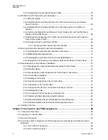
Page 261: ...nenten erhältlich die vom Benutzer ausgetauscht werden können Garantie und Reparaturen Tabelle 69 Kundendienstinformation Telefonnummern und Adressen von Servicezentren für Funkgeräte in Lateinamerika Land Telefonnummer Adresse Kolumbien 571 376 6990 MOTOROLA DE COLOMBIA SERVICE CENTRE Torre Banco Ganadero Carrera 7 No 71 52 Torre B piso 13 Oficina 1301 Bogota Mexiko 5252576700 MOTOROLA DE MEXICO ...

Page 262: ...e Empresarial Plaza Roble Edificio El Portico 1er Piso Centro de Negocios Internacional Guachepelin Escazu San Jose Ecuador 5932 264 1627 MOTOROLA DEL ECUADOR Autopist Gral Rumiñahui Pünte 2 Conjunto Puerta del Sol Este Ciudad Jardin Pasa E Casa 65 Quito Mexiko 52 555 257 6700 MOTOROLA DE MEXICO S A Calle Bosques de Alisos 125 Col Bosques de Las Lomas 05120 México D F Peru 511 211 0700 MOTOROLA DE...

Page 263: ...esse Venezuela 58212 901 4600 MOTOROLA DE LOS ANDES C A Ave Francisco de Miranda Centro Lido Torre A Piso 15 El Rosal Caracas 1060 68015000553 KC Anhang C Service Informationen Nord Mittel und Südamerika Feedback senden 133 ...

Page 264: ...Diese Seite wurde absichtlich leer gelassen ...
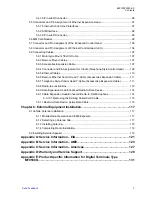
Page 265: ...stausch oder zur Reparatur abgedeckt ist sollte eine Prüfung des Produkts erfolgen bevor die Rücksendung an Motorola Solutions erfolgt Durch dieses Verfahren soll sichergestellt werden dass das Produkt korrekt programmiert wurde oder keine Schäden aufweist die nicht den Garantiebedingungen unterliegen Vor der Rücksendung eines Geräts an die zuständige Motorola Solutions Garantieannahmestelle wende...

Page 266: ...Diese Seite wurde absichtlich leer gelassen ...

Page 267: ...on maximal 4 5 A während PTT und von 30 mA kein Ethernet 90 mA Ethernet bei ausgeschaltetem Funkgerät vorliegt Frequenzbereich des Senders TMO 380 430 MHz MT953CG DMO 380 430 MHz MT953CG Frequenzbereich des Empfängers 380 430 MHz MT953CG Tabelle 72 Normale Ladebedingungen HF Nennleistung 10 W Audio Nennleistung 10 W bei 4 Ω 6 W bei 8 Ω Antennenimpedanz 50 Ω Betriebstemperatur Bereich 30 C bis 60 C...

Page 268: ...llation durchgebrannte Sicherungen NUR durch Sicherungen mit gleichen Werten ersetzen Verwenden Sie nie Sicherungen mit anderen Werten Sicherung für Zündungserkennungskab el PMKN4120 4 A Motorola Solutions Artikelnummer 6580283E02 68015000553 KC Anhang E Produktspezifische Informationen für digitale Mobilfunkgeräte vom Typ MT953CG 138 Feedback senden ...

Reviews: