MVME162 Functional Description
MVME162/D2
4-7
4
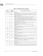
Port B is routed (via the module at J10) to the 25-pin DB25 connector marked
SERIAL PORT 2
on the MVME162 front panel. Port B is also routed to a DB9 (on
the MVME712x) or DB25 (on the MVME712M) connector on the MVME712
series transition module. It is identified there as Port 4.
Although both ports are connected to the same Z85230 Port B, there are several
considerations to keep in mind:
❏
On the MVME162 front panel, Port 2 can be connected to the TxC and RxC
clock signals which may be present on the DB25 connector. These
connections are made via header J12 on the MVME162 board (see Figures
2-3, 2-4, and 2-5 in Chapter 2). The TxC and RxC clock lines are also
available at Port 4 on MVME712M transition modules.
❏
On MVME712x transition modules, Port 4 is hard-wired as an EIA-232-D
DB9 DTE serial port. A ‘‘null modem’’ cable is necessary to use it as a DCE
port.
❏
On MVME712M transition modules, Port 4 can be configured as either a
DTE or DCE EIA-232-D serial port via jumper headers J19 and J18 on the
MVME712M. Port 4 can also be connected to the TxC and RxC clock
signals which may be present on the DB25 connector. These connections
are made via header J15 on the MVME712M (see Figure 2-3, sheets 3-6 in
Chapter 2).
❏
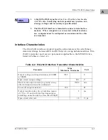
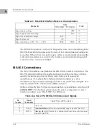
When Port B is configured as an EIA-530 interface, EIA-530 data transfers
normally occur through serial port 2 on the MVME162 front panel. The
MVME712 series transition module should be disconnected from the
MVME162.
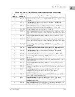
Although the signals are present at P2 (see Figure 2-5), the EIA-530
standard calls for a DB25 connector and balanced (not single-ended) lines;
these are not supported by the P2 adapter and MVME712 series transition
modules. System integrators who wish to use the EIA-530 signals at P2
must provide the appropriate connections.
Figure 2-3 (sheets 3-6), Figure 2-4 (sheets 3-4), and Figure 2-5 in Chapter 2
illustrate the factory configurations available for Port B. Note that the port
configurations shown in Figure 2-3, sheets 5 and 6 are not recommended for
synchronous applications because of the incorrect clock direction.
Summary of Contents for MVME162
Page 1: ...MVME162 Embedded Controller User s Manual MVME162 D2 ...
Page 6: ......
Page 10: ...x ...
Page 12: ...xii ...
Page 14: ...xiv ...
Page 52: ...Hardware Preparation and Installation 2 26 MVME162 Embedded Controller User s Manual 2 ...
Page 64: ...Operating Instructions 3 12 User s Manual 3 This page intentionally left blank ...
Page 78: ...Operating Instructions 3 26 User s Manual 3 ...
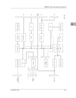
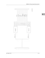
Page 92: ...Functional Description 4 14 User s Manual 4 Figure 4 1 MVME162 Main Module Block Diagram ...

