Serial Interconnections
A-2
User’s Manual
A
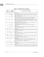
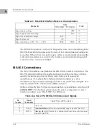
Table A-1. EIA-232-D Interconnections
Pin
Number
Signal
Mnemonic
Signal Name and Description
1
Not used.
2
TxD
Transmit Data
. Data to be transmitted; input to modem from terminal.
3
RxD
Receive Data
. Data which is demodulated from the receive line; output
from modem to terminal.
4
RTS
Request To Send
. Input to modem from terminal when required to
transmit a message. With RTS off, the modem carrier remains off. When
RTS is turned on, the modem immediately turns on the carrier.
5
CTS
Clear To Send
. Output from modem to terminal to indicate that message
transmission can begin. When a modem is used, CTS follows the off-to-on
transition of RTS after a time delay.
6
DSR
Data Set Ready
. Output from modem to terminal to indicate that the
modem is ready to send or receive data.
7
SG
Signal Ground
. Common return line for all signals at the modem
interface.
8
DCD
Data Carrier Detect
. Output from modem to terminal to indicate that a
valid carrier is being received.
9-14
Not used.
15
TxC
Transmit Clock
(DCE). Output from modem to terminal; clocks data from
the terminal to the modem.
16
Not used.
17
RxC
Receive Clock
. Output from terminal to modem; clocks input data from
the terminal to the modem.
18, 19
Not used.
20
DTR
Data Terminal Ready
. Input to modem from terminal; indicates that the
terminal is ready to send or receive data.
21
Not used.
22
RI
Ring Indicator
. Output from modem to terminal; indicates that an
incoming call is present. The terminal causes the modem to answer the
phone by carrying DTR true while RI is active..
23
Not used.
24
TxC
Transmit Clock
(DTE). Input to modem from terminal; same function as
TxC on pin 15.
25
BSY
Busy
. Input to modem from terminal; a positive EIA signal applied to this
pin causes the modem to go off-hook and make the associated phone busy.
Summary of Contents for MVME162
Page 1: ...MVME162 Embedded Controller User s Manual MVME162 D2 ...
Page 6: ......
Page 10: ...x ...
Page 12: ...xii ...
Page 14: ...xiv ...
Page 52: ...Hardware Preparation and Installation 2 26 MVME162 Embedded Controller User s Manual 2 ...
Page 64: ...Operating Instructions 3 12 User s Manual 3 This page intentionally left blank ...
Page 78: ...Operating Instructions 3 26 User s Manual 3 ...
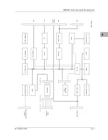
Page 92: ...Functional Description 4 14 User s Manual 4 Figure 4 1 MVME162 Main Module Block Diagram ...

