


Installation Instructions
MVME166IG/D2
2-9
2
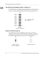
Other MPUs on the VMEbus can interrupt, disable, communicate with and
determine the operational status of the processor(s). One register of the GCSR
set includes four bits which function as location monitors to allow one
MVME166 processor to broadcast a signal to other MVME166 processors, if
any are present. All eight registers are accessible from any local processor as
well as from the VMEbus.
The MVME166 pr12 Vdc, -12 Vdc, and +5 Vdc power to the transition
modules through fuses F1, F3, and F4. The fused +5 Vdc power is also
provided to the 20-pin remote reset connector. These voltage sources are used
by the transition modules to power the serial port drivers and any LAN
transceivers connected to the transition module. The RPWR LED (DS3) on the
MVME166 front panel lights when all three voltages are available.
The MVME166 pr5 Vdc to the SCSI bus TERMPWR signal through
fuse F2, located near the front panel SCSI bus connector. The TPWR LED (DS5)
on the MVME166 front panel monitors the SCSI bus TERMPWR signal; when
the MVME166 is connected to an SCSI bus, either directly or via the
MVME712-07 module, the TPWR LED lights when there is SCSI terminator
power. Because any device on the SCSI bus can provide TERMPWR, the LED
does not directly indicate the condition of the fuse. If the LED is not
illuminated during SCSI bus operation, the fuse should be checked.
Summary of Contents for MVME166
Page 1: ...MVME166 Single Board Computer Installation Guide MVME166IG D2 ...
Page 12: ...xii ...
Page 14: ...xiv ...
Page 46: ...Hardware Preparation and Installation 2 10 MVME166 Single Board Computer Installation Guide 2 ...
Page 70: ...Debugger General Information 3 24 MVME166 Single Board Computer Installation Guide 3 ...
Page 114: ...Disk Tape Controller Data B 6 MVME166 Single Board Computer Installation Guide B ...
Page 116: ...Network Controller Data C 2 MVME166 Single Board Computer Installation Guide C ...


