Preparing the Board
http://www.motorola.com/computer/literature
1-7
1
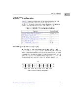
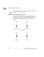
VME System Controller (J6)
The MVME177P can be VMEbus system controller. The system controller
function is enabled/disabled by jumpers on header J6. When the
MVME177P is system controller, the SCON LED is turned on. The
VMEchip2 may be configured as a system controller as follows.
SRAM Backup Power Source (J9)
Header J9 determines the source for onboard static RAM backup power on
the MVME177P. In the factory configuration, 5V standby
voltage serves as primary and secondary power source (the onboard
battery is disconnected). The backup power configurations available for
onboard SRAM through header J9 are illustrated in the following diagram.
System Controller
J6
1
3
J6
1
3
Auto System Controller
(Factory Configuration)
J6
1
3
Not System Controller
J9
2
1
6
5
Primary 5V STBY
Secondary 5V STBY
(Factory Configuration)
J9
2
1
6
5
Primary Onboard Battery
Secondary Onboard Battery
J9
2
1
6
5
Primary 5V STBY
Secondary Onboard Battery
J9
2
1
6
5
Primary Onboard Battery
Secondary 5V STBY
Summary of Contents for MVME177P
Page 1: ...MVME177P Single Board Computer Installation and Use V177PA IH1 Edition of October 2000 ...
Page 10: ...x ...
Page 12: ...xii ...
Page 14: ...xiv ...
Page 34: ...1 16 Computer Group Literature Center Web Site Hardware Preparation and Installation 1 ...
Page 48: ...2 14 Computer Group Literature Center Web Site Startup and Operation 2 ...
Page 92: ...C 2 Computer Group Literature Center Web Site Network Controller Data C ...
Page 98: ...D 6 Computer Group Literature Center Web Site Disk Tape Controller Data D ...
Page 108: ...Index IN 6 Computer Group Literature Center Web Site I N D E X ...

