2-6
Computer Group Literature Center Web Site
Startup and Operation
2
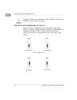
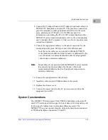
4. Headers J10 and J11 configure serial port 4 to drive or receive clock
signals provided by the RTXC and TRXC signal lines. The
MVME177P factory configuration has port 4 set to receive both
signals. Refer to the instructions in Chapter 1 if your application
requires reconfiguring port 4.
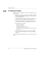
5. Verify that the settings of configuration switches S3 (Petra SDRAM
size) and S4 (board EPROM/Flash mode) are appropriate for your
memory controller emulation.
6. Refer to the setup procedure for your particular chassis or system for
details concerning the installation of the MVME177P.
7. Connect the terminal to be used as the 177Bug system console to the
default EIA-232-D port at MVME177P Serial Port 1 (Serial Port 2
on the MVME712M transition module). Set the terminal up as
follows:
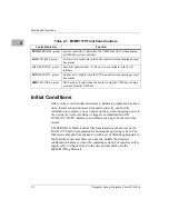
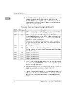
Table 2-2. General-Purpose Configuration Bits (J1)
Bit No.
J1 Segment
Function
GPI0
1-2
When set to 1 (high), instructs the debugger to use local static RAM for
its work page (variables, stack, vector tables, etc.).
GPI1
3-4
When set to 1 (high), instructs the debugger to use the default
setup/operation parameters in ROM instead of the user setup/operation
parameters in NVRAM. The effect is the same as pressing the
RESET
and
ABORT
switches simultaneously.
This feature can be helpful in the event the user setup is corrupted or
does not meet a sanity check. Refer to the ENV command description
for the Flash/ROM defaults.
GPI2
5-6
Reserved for future use.
GPI3
7-8
When set to 0 (low), informs the debugger that it is executing out of
EPROM. When set to 1 (high), informs the debugger that it is executing
from Flash memory.
GPI4
9-10
Open to your application.
GPI5
11-12
Open to your application.
GPI6
13-14
Open to your application.
GPI7
15-16
Open to your application.
Summary of Contents for MVME177P
Page 1: ...MVME177P Single Board Computer Installation and Use V177PA IH1 Edition of October 2000 ...
Page 10: ...x ...
Page 12: ...xii ...
Page 14: ...xiv ...
Page 34: ...1 16 Computer Group Literature Center Web Site Hardware Preparation and Installation 1 ...
Page 48: ...2 14 Computer Group Literature Center Web Site Startup and Operation 2 ...
Page 92: ...C 2 Computer Group Literature Center Web Site Network Controller Data C ...
Page 98: ...D 6 Computer Group Literature Center Web Site Disk Tape Controller Data D ...
Page 108: ...Index IN 6 Computer Group Literature Center Web Site I N D E X ...

