Equipment Required
MVME197LE/D2
1-5
1
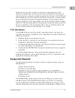
While the exact amount of airflow required for cooling depends on the
ambient air temperature and the type, number, and location of boards and
other heat sources, adequate cooling can usually be achieved with 10 CFM and
490 LFM flowing over the module. Less airflow is required to cool the module
in environments having lower maximum ambients. Under more favorable
thermal conditions, it may be possible to operate the module reliably at higher
than 55° C with increased airflow. It is important to note that there are several
factors, in addition to the rated CFM of the air mover, which determine the
actual volume and speed of air flowing over a module.
FCC Compliance
The MVME197LE was tested in an FCC-compliant chassis, and meets the
requirements for Class A equipment. FCC compliance was achieved under the
following conditions:
1.
Shielded cables on all external I/O ports.
2.
Cable shields are connected to earth ground via metal shell connectors
bonded to a conductive module front panel.
3.
Conductive chassis rails connected to earth ground. This provides the path
for connecting shields to earth ground.
4.
All chassis and MVME197LE front panel attachment screws are properly
tightened.
For minimum RF emissions, it is essential that the conditions above be
implemented; failure to do so could compromise the FCC compliance of the
equipment containing the module.
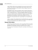
Equipment Required
The following equipment is required to make a complete system using the
MVME197LE:
System console terminal
Disk drives and controllers
MVME712 series transition modules (MVME712-12, MVME712-13,
MVME712A, MVME712AM, MVME712B, or MVME712M); P2 or LCP2
Adapter Boards
Operating system
The MVME197Bug debug monitor firmware (197Bug) is provided in the
FLASH memory on the MVME197LE module. It provides over 50 debug,
up/down line load, and disk bootstrap load commands, as well as a set of
onboard diagnostics and a one-line assembler/disassembler. 197Bug includes
Summary of Contents for MVME197LE
Page 1: ...MVME197LE Single Board Computer User s Manual MVME197LE D2 ...
Page 12: ...xii ...
Page 14: ...xiv ...
Page 22: ...Hardware Preparation and Installation 2 2 User s Manual 2 ...
Page 30: ...Hardware Preparation and Installation 2 10 User s Manual 2 ...
Page 37: ...Memory Maps MVME197LE D2 3 7 3 ...
Page 40: ...Operating Instructions 3 10 User s Manual 3 ...
Page 42: ...Operating Instructions 3 12 User s Manual 3 ...
Page 44: ...Operating Instructions 3 14 User s Manual 3 ...
Page 46: ...Operating Instructions 3 16 User s Manual 3 ...
Page 48: ...Operating Instructions 3 18 User s Manual 3 ...
Page 60: ...Functional Description 4 2 User s Manual 4 ...

