Operating Instructions
3-6
User’s Manual
3
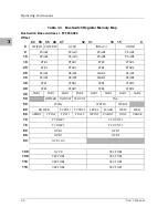
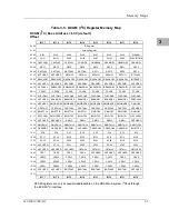
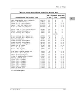
Table 3-3. BusSwitch Register Memory Map
BusSwitch Base Address = $FFF00000
Offset
63
56
55
48
47
32
31
16
15
0
0
CHIPID CHIPREV
GCSR
IODATA
IODIR
8
PSAR1
PEAR1
PSAR2
PEAR2
10
PSAR3
PEAR3
PSAR4
PEAR4
18
PTR1
PTSR1
PTR2
PTSR2
20
PTR3
PTSR3
PTR4
PTSR4
28
SSAR1
SEAR1
SSAR2
SEAR2
30
SSAR3
SEAR3
SSAR4
SEAR4
38
STR1
STSR1
STR2
STSR2
40
STR3
STSR3
STR4
STSR4
48
PAR1
PAR2
PAR3
PAR4
SAR1
SAR2
SAR3
SAR4
50
BTIMER PADJUST PCOUNT
PAL
58
WPPA
WPTPA
WPPAT
60
ROMCR
TCTRL1
TCTRL2
LEVEL
MASK
ISEL0
ISEL1
68
ABORT
CPINT
TINT1
TINT2
WPINT
PALINT
XINT
VBASE
70
TCOMP1
TCOUNT1
78
TCOMP2
TCOUNT2
80
GPR1
GPR2
88
GPR3
GPR4
90
XCTAGS
100
XCCR
VECTOR1
108
VECTOR2
VECTOR3
110
VECTOR4
VECTOR5
118
VECTOR6
VECTOR7
Summary of Contents for MVME197LE
Page 1: ...MVME197LE Single Board Computer User s Manual MVME197LE D2 ...
Page 12: ...xii ...
Page 14: ...xiv ...
Page 22: ...Hardware Preparation and Installation 2 2 User s Manual 2 ...
Page 30: ...Hardware Preparation and Installation 2 10 User s Manual 2 ...
Page 37: ...Memory Maps MVME197LE D2 3 7 3 ...
Page 40: ...Operating Instructions 3 10 User s Manual 3 ...
Page 42: ...Operating Instructions 3 12 User s Manual 3 ...
Page 44: ...Operating Instructions 3 14 User s Manual 3 ...
Page 46: ...Operating Instructions 3 16 User s Manual 3 ...
Page 48: ...Operating Instructions 3 18 User s Manual 3 ...
Page 60: ...Functional Description 4 2 User s Manual 4 ...


