MVME197LE Functional Description
MVME197LE/D2
4-9
4
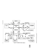
other external sources (PALINT and IRQ). The BusSwitch may also generate
the non-maskable interrupt (NMI) signal to the MPU from the ABORT push-
button switch. Refer to the BusSwitch, PCCchip2, and VMEchip2 chapters in the
MVME197LE, MVME197DP, and MVME197SP Single Board Computers
Programmer’s Reference Guide for more detailed information.
Summary of Contents for MVME197LE
Page 1: ...MVME197LE Single Board Computer User s Manual MVME197LE D2 ...
Page 12: ...xii ...
Page 14: ...xiv ...
Page 22: ...Hardware Preparation and Installation 2 2 User s Manual 2 ...
Page 30: ...Hardware Preparation and Installation 2 10 User s Manual 2 ...
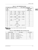
Page 37: ...Memory Maps MVME197LE D2 3 7 3 ...
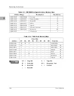
Page 40: ...Operating Instructions 3 10 User s Manual 3 ...
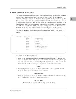
Page 42: ...Operating Instructions 3 12 User s Manual 3 ...
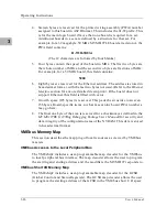
Page 44: ...Operating Instructions 3 14 User s Manual 3 ...
Page 46: ...Operating Instructions 3 16 User s Manual 3 ...
Page 48: ...Operating Instructions 3 18 User s Manual 3 ...
Page 60: ...Functional Description 4 2 User s Manual 4 ...

