O M O T O R O L A
TABLE 2-1.
Serial P o r t #
Serial P o r t and Associated Header I d e n t i f i c a t i o n
Associated A s s o c i a t e d
"Connect t o Terminal" " C o n n e c t t o Modem"
Jumper Array
J
u
m
p
e
r
Array
1
J21
J22
2
J23
J24
3
J17
J18
4
J19
J20
5
J13
J14
6
J15
J16
7
J9
J10
8
J11
J12
HARDWARE PREPARATION
CHAPTER 2
HARDWARE PREPARATION
2.1 INTRODUCTION
2
This chapter provides hardware preparation and i n s t a l l a t i o n i n s t r u c t i o n s f o r
the MVME710 module.
2.2 HARDWARE PREPARATION
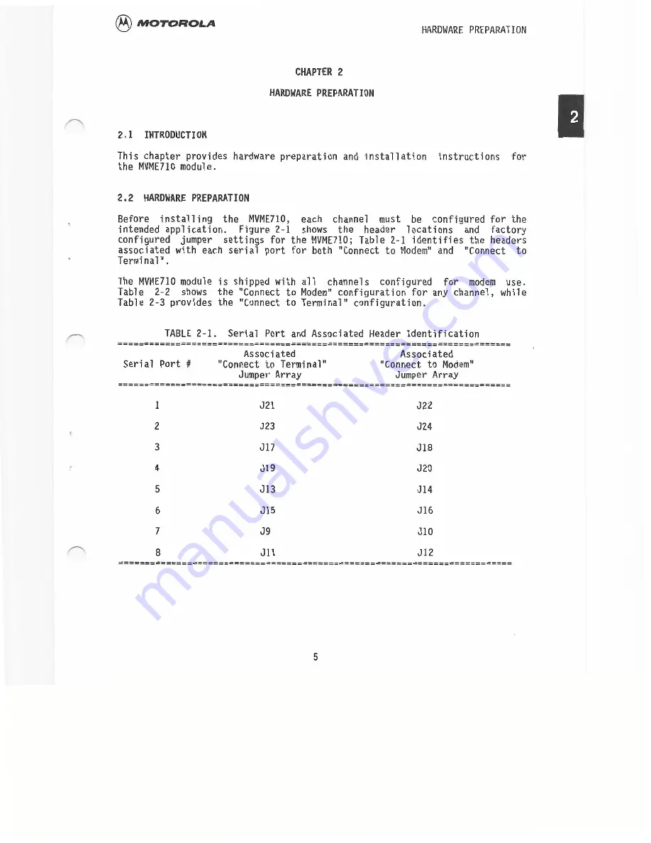
Before i n s t a l l i n g t h e MVME710, e a c h c h a n n e l m u s t b e c o n f i g u r e d f o r t h e
intended a p p l i c a t i o n . F i g u r e 2-1 shows t h e h e a d e r l o c a t i o n s a n d f a c t o r y
configured j u m p e r s e t t i n g s f o r t h e MVME710; Ta b l e 2-1 i d e n t i f i e s t h e headers
associated w i t h each s e r i a l p o r t f o r both "Connect t o Modem" and "Connect t o
Terminal".
The MVME710 module i s shipped w i t h a l l c h a n n e l s c o n f i g u r e d f o r modem u s e .
Table 2 - 2 shows t h e "Connect t o Modem" c o n f i g u r a t i o n f o r any channel, w h i l e
Table 2-3 provides t h e "Connect t o Terminal" c o n f i g u r a t i o n .
5


