2-6 Administrator’s Handbook
8.
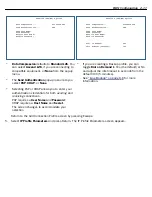
To add a circuit, select
Add Circuit
and press Return. The Add Circuit screen appears.
•
Enter a name for the circuit in the Circuit Name field.
•
Toggle
Circuit Enabled
to Yes.
•
Enter the Vir tual Path Identifier and the Vir tual Channel Identifier in the
Circuit VPI
and
Circuit VCI
fields, respectively.
•
The
Peak Cell Rate
field is editable. Motorola Netopia® Embedded Software Version 8.7.4 suppor ts
three ATM classes of ser vice for data connections: Unspecified Bit Rate (UBR), Constant Bit Rate
(CBR), and Variable Bit Rate (VBR). You can configure these classes of ser vice on a per VC basis. The
ATM Circuits Configuration
Show/Change Circuit...
Add Circuit...
Delete Circuit...
Add Circuit
Circuit Name: Circuit 2
Circuit Enabled: Yes
Circuit VPI (0-255): 0
Circuit VCI (32-65535): +-------------+
+-------------+
QoS... | UBR |
Peak Cell Rate (0 = line rate): | CBR |
| VBR |
+-------------+
Use Connection Profile... Default Profile
Use Default Profile for Circuit
ADD Circuit NOW CANCEL
Summary of Contents for Netopia Embedded Software
Page 10: ...x Administrator s Handbook ...
Page 16: ...1 6 Administrator s Handbook ...
Page 44: ...2 28 Administrator s Handbook ...
Page 108: ...3 64 Administrator s Handbook ...
Page 176: ...5 34 Administrator s Handbook ...
Page 202: ...6 26 Administrator s Handbook ...
Page 244: ...7 42 Administrator s Handbook ...
Page 340: ...Index 6 ...


