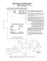
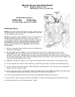
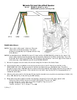
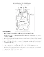
background image

MOTOROLA EXTERNAL (AMPLIFIED) SPEAKER MODS

Accumulated over time by: Tom Hammond, NØSS

10 January 2008

Corrections are encouraged, please send to: nØss@arrl.net

(note: In the link above, the 'Ø' is the numeral ZERO, not an 'oh')

Summary of Contents for NSN6027A

Page 1: ...LA EXTERNAL AMPLIFIED SPEAKER MODS Accumulated over time by Tom Hammond NØSS 10 January 2008 Corrections are encouraged please send to nØss arrl net note In the link above the Ø is the numeral ZERO not an oh ...

Page 2: ...erence Step 1 Loosen the two wing nuts one on each side several turns and remove the mounting bracket from the speaker Step 2 Temporarily position the speaker and mounting bracket to verity the desired mounting location Make sure that the speaker will not interfere with the operation of the vehicle preferable placement is on the passenger side of the vehicle and that the speaker front is not block...

Page 3: ...e pictorial diagram locate the correct hole location and insert the sockets into the rear numbered end of the connector A miniature screwdriver is helpful to push the sockets into the connector The rear of the socket will be recessed into it s hole about 1 16 when properly seated 6 Slide the 1 4 shrink tubing up the cables with the jumpers inside the tubing until it is about 3 8 from the back of t...

Page 4: ...ustration to the right DO NOT CLIP the following wires connected to the four center pins of the connector RED BLK 12VDC YEL AF INPUT BRN DC GND WHT AF GND 3 Install two solder bridge SHORT jumpers as shown in the outset above 4 Cut the four remaining wires from the 8 Pin plug to a length of about 2 and strip 1 8 of insulation from each wire 5 Install and insulate new DC power leads connecting them...

Page 5: ...Motorola External Amplified Speaker Models TLN2660A printed on Speaker Case TRN5897A printed on AF Amp PC Board ...

Page 6: ...Motorola External Amplified Speaker Models TRN5898B1S printed on AF Amp PC Board ...

Page 7: ...radio BLU WHT wires to the transformer s 8 Ohm secondary and connect the primary to the BLU WHT pads on the PC board This method will also produce more audio output than method 1 There are two rectangular pads associated with the BLU and WHT pads on the PC board If you remove the solder from these two rectangular pads the empty holes make a nice attachment point for the secondary wires from the is...

Page 8: ... the screws holding the PC board to the internal frame 2 NOTE that all control cable wires are installed in a semi circle around a cutout in the PC board Also note that on the COMPONENT side of the PC board several of the holes are labeled for easy identification later This will be important in future steps CONFIRM that the component side labels MATCH those labels which have been added to the PC b...

Page 9: ...COMPONENT side of the PC board several of the holes are labeled for easy identification later This will be important in future steps CONFIRM that the component side labels MATCH those labels which have been added to the PC board drawing shown above NOTE that although the pad at the bottom of the semi circle is NOT labeled it is actually the ground GND pad for the circuit 3 CAREFULLY desolder and r...

Page 10: ...nternal frame 2 All control cable wires are installed in a semi circle around a cutout in the PC board Also note that on the COMPONENT side of the PC board several of the holes are labeled for easy identification later This will be important in future steps CONFIRM that the component side labels MATCH those labels which have been added to the PC board drawing shown above If the numbers on do not m...

Page 11: ...nd a cutout in the PC board Also note that several of the holes 1 5 8 11 are numbered on the COMPONENT side of the PC board for easy identification later This will be important in future steps 4 With the exception of the speaker wires connected to holes 3 4 CAREFULLY desolder and remove ALL wires from the remaining PC board holes 5 Install new DC power leads connecting them to holes 10 GND and 11 ...

Page 12: ...ED speakers especially those which are completely contained within PLASTIC enclosures with enclosure backs which appear to be form fitted around the back of the speaker The NSN6026A is one example While this is a VERY NICE 3 2 Ohm possibly 4 Ohm speaker it is NOT an amplified design and requires NO modifications If you are looking for a Motorola AMPLIFIED speaker be certain that is what you are pu...

Reviews: