Engl
ish
INSTALLATION PROCEDURE
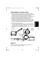
1. Determine the installation location of the GNSS magnetic mount
antenna, ensuring that the mounting surface is as flat as possible and
location is clean from debris and free of any obstruction. Surface must
be of a ferrous based material.
2. Place the antenna at the selected location. The antenna’s strong
magnetic force will secure it to the vehicle’s surface.
3. To secure the antenna more firmly on the vehicle’s surface, drill holes
using the pattern shown in Figure 1. To ensure a long term, water-tight
seal, it is recommended that a bead of silicone sealant be applied
around all the holes.
SERVICE
The GNSS magnetic mount antenna is not repairable. Please order a
replacement as necessary.
Figure 1
Notes: Unless otherwise specified
1. The GNSS magnetic mount antenna includes an active GPS/GLONASS antenna with
an option for magnetic or screw mount installation. The optimum location for mounting
the GNSS plus is a flat level surface, free of obstruction, offering a clear view of the
horizon and above in all directions.
2. Dimensions in parenthesis (inch [mm]) are nominal values and are given for reference
only
(2.323 [58.99])
Bottom label
Base with magnets
(16.4 feet [5 meters])
(2.051 [52.11])
Hole(s) for mounting
cast base 0.071
Hole(s) to be tapped
M2.5 machine screw
1.06 (23)
0.57 (13)
1.14 (25)
(0.536 [13.60])
Straight male SMA connector
Heat shrink tube
PVC strain relief
Coaxial cable
1.5DS-QEHV black
Plastic radome
391X series
6871962L02.book Page 1 Monday, September 29, 2014 7:03 PM
Summary of Contents for PMAN4010
Page 2: ...6871962L02 book Page 2 Monday September 29 2014 7 03 PM ...
Page 16: ...Note 6871962L02 book Page 1 Monday September 29 2014 7 03 PM ...
Page 17: ...Note 6871962L02 book Page 2 Monday September 29 2014 7 03 PM ...
Page 18: ...Note 6871962L02 book Page 3 Monday September 29 2014 7 03 PM ...
Page 19: ...6871962L02 book Page 1 Monday September 29 2014 7 03 PM ...


