background image

603 Hardware Specifications

13

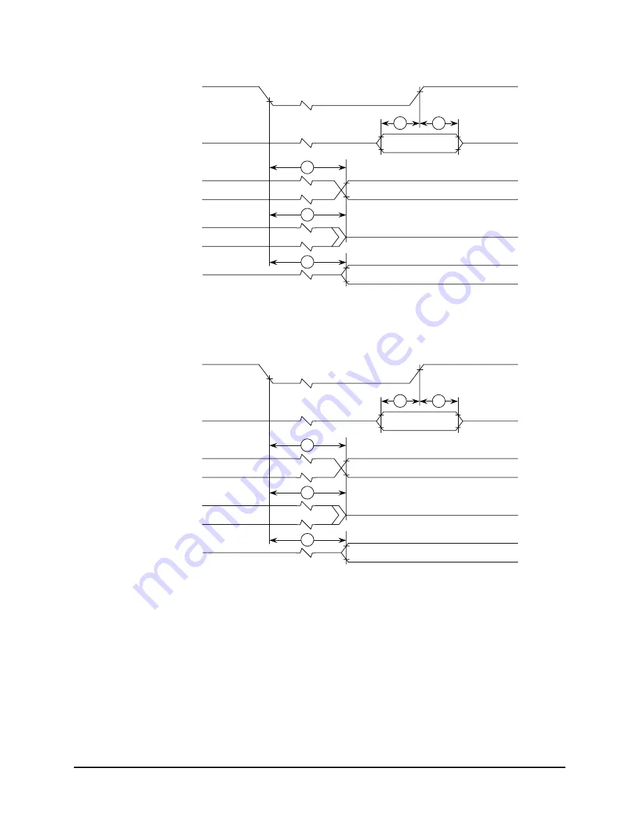
Figure 7 provides the boundary-scan timing diagram.

Figure 7. Boundary-Scan Timing Diagram

Figure 8 provides the test access port timing diagram.

Figure 8. Test Access Port Timing Diagram

6

7

Input Data Valid

8

9

8

Output Data Valid

Output Data Valid

TCK

Data Inputs

Data Outputs

Data Outputs

Data Outputs

VM

VM

10

11

Input Data Valid

12

13

12

Output Data Valid

Output Data Valid

TCK

TDI, TMS

TDO

TDO

TDO

VM

VM

Summary of Contents for PowerPC 603

Page 1: ...tion set computing RISC microprocessors In this document the term 603 is used as an abbreviation for the phrase PowerPC 603 microprocessor The PowerPC 603 microprocessors are available from Motorola as MPC603 and from IBM as PPC603 This document contains pertinent physical characteristics of the 603 For functional characteristics refer to the PowePC 603 RISC Microprocessor User s Manual This docum...

Page 2: ...iency and throughput for 603 based systems Most integer instructions execute in one clock cycle The FPU is pipelined so a single precision multiply add instruction can be issued every clock cycle The 603 provides independent on chip 8 Kbyte two way set associative physically addressed caches for instructions and data and on chip instruction and data memory management units MMUs The MMUs contain 64...

Page 3: ...itional branches Instruction fetch unit capable of fetching two instructions per clock from the instruction cache A six entry instruction queue that provides lookahead capability Independent pipelines with feed forwarding that reduces data dependencies in hardware 8 Kbyte data cache two way set associative physically addressed LRU replacement algorithm 8 Kbyte instruction cache two way set associa...

Page 4: ...Thermal Characteristics This section provides the AC and DC electrical specifications and thermal characteristics for the 603 1 4 1 DC Electrical Characteristics The tables in this section describe the 603 DC electrical characteristics Table 1 provides the absolute maximum ratings Table 1 Absolute Maximum Ratings Characteristic Symbol Value Unit Core supply voltage Vdd 0 3 to 4 0 V PLL supply volt...

Page 5: ...ristics Characteristic Symbol Value Rating Motorola wire bond CQFP package die junction to case thermal resistance typical θJC 2 2 C W IBM C4 CQFP package die junction to heat sink base thermal resistance typical θJS 1 1 C W Note Refer to Section 1 8 System Design Information for more details about thermal management Table 4 DC Electrical Specifications Vdd 3 3 5 V dc GND 0 V dc 0 Tj 105 C Charact...

Page 6: ...0 V dc 0 Tj 105 C CPU Clock SYSCLK Processor Core Frequency Unit 66 67 MHz 80 MHz Full On Mode Typical Maximum 1 8 2 0 W 2 5 2 9 W Doze Mode Typical 740 800 mW Nap Mode Typical 160 160 mW Sleep Mode Typical 125 130 mW Sleep Mode PLL Disabled Typical 70 40 mW Sleep Mode PLL and SYSCLK Disabled Typical 2 2 mW Note These values apply for all valid PLL_CFG 0 3 settings and do not include output driver...

Page 7: ...0 MHz 1 SYSCLK cycle time 40 0 60 0 30 0 60 0 25 0 60 0 ns 2 3 SYSCLK rise and fall time 2 0 2 0 2 0 ns 2 4 SYSCLK duty cycle measured at 1 4 V 40 0 60 0 40 0 60 0 40 0 60 0 3 SYSCLK jitter 150 150 150 ps 4 603 internal PLL relock time 100 100 100 µs 3 5 Notes 1 Caution The SYSCLK frequency and PLL_CFG 0 3 settings must be chosen such that the resulting SYSCLK bus frequency CPU core frequency and ...

Page 8: ...s invalid input hold for DRTRY QACK and TLBISYNC 0 0 0 ns 4 6 Notes 1 All input specifications are measured from the TTL level 0 8 or 2 0 V of the signal in question to the 1 4 V of the rising edge of the input SYSCLK Both input and output timings are measured at the pin see Figure 2 2 Address data transfer attribute input signals are composed of the following A 0 31 AP 0 3 TT 0 4 TC 0 1 TBST TSIZ...

Page 9: ...ram for the 603 Figure 2 Input Timing Diagram Figure 3 provides the mode select input timing diagram for the 603 Figure 3 Mode Select Input Timing Diagram VM SYSCLK ALL INPUTS VM Midpoint Voltage 1 4 V 10a 10b 11a 11b MODE PINS HRESET VM VM Midpoint Voltage 1 4 V 10c 11c ...

Page 10: ... 0 10 0 ns 19 SYSCLK to ARTRY precharge enable 0 2 tsysclk 1 0 0 2 tsysclk 1 0 0 2 tsysclk 1 0 ns 3 5 8 20 Maximum delay to ARTRY precharge 1 0 1 2 1 0 tsysclk 5 8 21 SYSCLK to ARTRY high impedance after precharge 2 0 2 25 2 0 tsysclk 5 8 Notes 1 All output specifications are measured from the 1 4 V of the rising edge of SYSCLK to the TTL level 0 8 V or 2 0 V of the signal in question Both input a...

Page 11: ...ndent of SYSCLK Vdd 3 3 5 V dc GND 0 V dc CL 50 pF 0 Tj 105 C Num Characteristic Min Max Unit Notes TCK frequency of operation 0 16 MHz 1 TCK cycle time 62 5 ns 2 TCK clock pulse width measured at 1 4 V 25 ns 3 TCK rise and fall times 0 3 ns 4 TRST setup time to TCK rising edge 13 ns 1 5 TRST assert time 40 ns 6 Boundary scan input data setup time 6 ns 2 SYSCLK 12 14 13 15 16 16 TS ARTRY ABB DBB V...

Page 12: ...I data setup time 0 ns 11 TMS TDI data hold time 25 ns 12 TCK to TDO data valid 4 24 ns 13 TCK to TDO high impedance 3 15 ns Notes 1 TRST is an asynchronous signal The setup time is for test purposes only 2 Non test signal input timing with respect to TCK 3 Non test signal output timing with respect to TCK Table 9 JTAG AC Timing Specifications Independent of SYSCLK Continued Vdd 3 3 5 V dc GND 0 V...

Page 13: ...am Figure 8 provides the test access port timing diagram Figure 8 Test Access Port Timing Diagram 6 7 Input Data Valid 8 9 8 Output Data Valid Output Data Valid TCK Data Inputs Data Outputs Data Outputs Data Outputs VM VM 10 11 Input Data Valid 12 13 12 Output Data Valid Output Data Valid TCK TDI TMS TDO TDO TDO VM VM ...

Page 14: ...156 155 154 153 152 151 150 149 148 147 146 145 144 143 142 141 140 139 138 137 136 135 134 133 132 131 130 129 128 127 126 125 124 123 122 121 OVDD GND OGND CI WT QACK TBEN TLBISYNC RSRV AP0 AP1 OVDD OGND AP2 AP3 CSE TC0 TC1 OVDD CLK_OUT OGND BR APE DPE CKSTP_OUT CKSTP_IN HRESET PLL_CFG0 SYSCLK PLL_CFG1 PLL_CFG2 AVDD PLL_CFG3 VDD GND LSSD_MODE L1_TSTCLK L2 _TSTCLK TRST TCK TMS TDI TDO TSIZ0 TSIZ1...

Page 15: ...APE 218 Low Output ARTRY 32 Low I O AVDD 209 High Input BG 27 Low Input BR 219 Low Output CI 237 Low Output CLK_OUT 221 Output CKSTP_IN 215 Low Input CKSTP_OUT 216 Low Output CSE 225 High Output DBB 145 Low I O DBDIS 153 Low Input DBG 26 Low Input DBWO 25 Low Input DH 0 31 115 114 113 110 109 108 99 98 97 94 93 92 91 90 89 87 85 84 83 82 81 80 78 76 75 74 73 72 71 68 67 66 High I O DL 0 31 143 141...

Page 16: ... 104 112 121 128 138 148 163 173 183 194 222 229 240 High Input PLL_CFG 0 3 213 211 210 208 High Input QACK 235 Low Input QREQ 31 Low Output RSRV 232 Low Output SMI 187 Low Input SRESET 189 Low Input SYSCLK 212 Input TA 155 Low Input TBEN 234 High Input TBST 192 Low I O TC 0 1 224 223 High Output TCK 201 Input TDI 199 High Input TDO 198 High Output TEA 154 Low Input TLBISYNC 233 Low Input TMS 200 ...

Page 17: ...ided in the following list The package type is 32 mm x 32 mm 240 pin ceramic quad flat pack Package outline 32 mm x 32 mm Interconnects 240 Pitch 0 5 mm 20 mil Maximum module height 4 15 mm TS 149 Low I O TT 0 4 191 190 185 184 180 High I O VDD 4 14 24 34 44 59 122 137 147 157 167 177 207 High Input WT 236 Low Output XATS 150 Low I O Notes 1 These are test signals for factory use only and must be ...

Page 18: ... the Motorola Wire Bond CQFP Package Reduced pin count shown for clarity 60 pins per side Min Max A 30 86 31 75 B 34 6 BSC C 3 75 4 15 D 0 5 BSC E 0 18 0 30 F 3 10 3 90 G 0 13 0 175 H 0 45 0 55 J 0 25 AA 1 80 REF AB 0 95 REF θ1 2 6 θ2 1 7 R 0 15 REF H AB θI R R AA θ2 H Pin 240 C A B Pin 1 D E Not to scale G F J Die Wire Bonds Ceramic Body Alloy 42 Leads Notes 1 BSC Between Standard Centers 2 All m...

Page 19: ...rovided in the following list The package type is 32 mm x 32 mm 240 pin ceramic quad flat pack Package outline 32 mm x 32 mm Interconnects 240 Pitch 0 5 mm Lead plating Ni Au Solder joint Sn PB 10 90 Lead encapsulation Epoxy Solder bump encapsulation Epoxy Maximum module height 3 1 mm Co planarity specification 0 08 mm Note No solvent can be used with the C4 CQFP package See Appendix A General Han...

Page 20: ...Reduced pin count shown for clarity 60 pins per side min max A 31 8 32 2 B 34 4 34 8 C 2 33 2 93 D 0 45 0 55 E 0 18 0 28 F 0 585 0 685 G 0 12 0 20 H 0 40 0 60 Jmin 0 30 0 40 Ang 0 0 5 0 Rad 0 25 Clip Leadframe Chip Tape Cast Ceramic Epoxy Dam Urethane Solder Bump Encapsulant H Jmin Radius 0 08 F G A B E 0 13 TOTAL s A B C 0 13 TOTAL s A B 0 08 TOTAL M A B D A Pin 240 Pin 1 Not to scale All measure...

Page 21: ...x 8x 16 6 133 20 160 25 200 0100 2x 2x 66 6 133 80 160 0101 2x 4x 33 3 133 40 160 50 200 1000 3x 2x 60 120 75 150 1001 3x 4x 50 200 60 240 1100 4x 2x 66 6 133 80 160 0011 PLL bypass 1111 Clock off Notes 1 The sample bus to core frequencies shown are for reference only 2 Some PLL configurations may select bus CPU or PLL frequencies which are not supported by the 603 see Section 1 4 2 2 Input AC Spe...

Page 22: ... for the Vdd pins 220 pF ceramic 0 01 µF ceramic and 0 1 µF ceramic Suggested values for the OVdd pins 0 01 µF ceramic 0 1 µF ceramic and 10 µF tantalum Only SMT surface mount technology capacitors should be used to minimize lead inductance In addition it is recommended that there be several bulk storage capacitors distributed around the PCB feeding the Vdd and OVdd planes to enable quick rechargi...

Page 23: ... control design is primarily dependent upon the system level design the heat sink airflow and thermal interface material To reduce the die junction temperature heat sinks may be attached to the package by several methods adhesive or spring clip to holes in the printed circuit board see Figure 13 This spring force should not exceed 5 5 pounds of force Figure 13 Package Exploded Cross Sectional View...

Page 24: ...l performance of three thin sheet thermal interface materials silicone graphite oil floroether oil a bare joint and a joint with thermal grease as a function of contact pressure As shown the performance of these thermal interface materials improves with increasing contact pressure The use of thermal grease significantly reduces the interface thermal resistance That is the bare joint results in a t...

Page 25: ...rfaces and adhesive materials provided by the following vendors Dow Corning Corporation 517 496 4000 Dow Corning Electronic Materials P O Box 0997 Midland MI 48686 0997 Chomerics Inc 617 935 4850 77 Dragon Court Woburn MA 01888 4850 Thermagon Inc 216 741 7659 3256 West 25th Street Cleveland OH 44109 1668 0 0 5 1 1 5 2 0 1 0 2 0 3 0 4 0 5 0 6 0 7 0 8 0 Graphite Oil Sheet 0 005 inch Silicone Sheet 0...

Page 26: ...nk base to ambient thermal resistance Pd is the power dissipated by the device During operation the die junction temperatures Tj should be maintained less than the value specified in Table 2 The temperature of the air cooling the component greatly depends upon the ambient inlet air temperature and the air temperature rise within the electronic cabinet An electronic cabinet inlet air temperature Ta...

Page 27: ...operating temperature is not only a function of the component level thermal resistance but the system level design and its operating conditions In addition to the component s power consumption a number of factors affect the final operating die junction temperature airflow board population local heat flux of adjacent components heat sink efficiency heat sink attach heat sink placement next level in...

Page 28: ...tion of the IBM part number for the 603 Figure 18 IBM Part Number Key Table 12 Ordering Information for the PowerPC 603 Microprocessor Package Type Maximum Internal Frequency Maximum Bus Frequency Required PLL_CFG 0 3 Setting Part Numbers Motorola IBM Motorola IBM Wire bond CQFP C4 CQFP 80 MHz 40 MHz 0100 MPC603AFE80CC PPC603 FX 080 2 66 67 MHz 33 33 MHz 0100 MPC603AFE66CC PPC603 FX 066 2 66 67 MH...

Page 29: ...suitable for continuous operation under business office environments Operating environment 10 C to 40 C 8 to 80 relative humidity Storage environment 1 C to 60 C up to 80 relative humidity Shipping environment 40 C to 60 C 5 to 100 relative humidity This component is qualified to meet JEDEC moisture Class 2 After expiration of shelf life packages may be baked at 120 C 10 5 C for 4 hours minimum an...

Page 30: ... reflow De ionized D I water if water soluble paste is used Cleaner requirements conveyorized in line Minimum of four washing chambers Pre clean chamber top and bottom sprays minimum top side pressure of 25 psig water temperature of 70 C minimum dwell time of 24 seconds minimum water is not re used water flow rate of 30 liters minute Wash chamber 1 top and bottom sprays minimum top side pressure o...

Page 31: ...IBM convey any license under their respective intellectual property rights nor the rights of others Neither Motorola nor IBM makes any claim warranty or representation express or implied that the products described in this document are designed intended or authorized for use as components in systems intended for surgical implant into the body or other applications intended to support or sustain li...

Reviews: