


603 Hardware Specifications
21
1.8 System Design Information
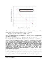
This section provides electrical and thermal design recommendations for successful application of the 603.
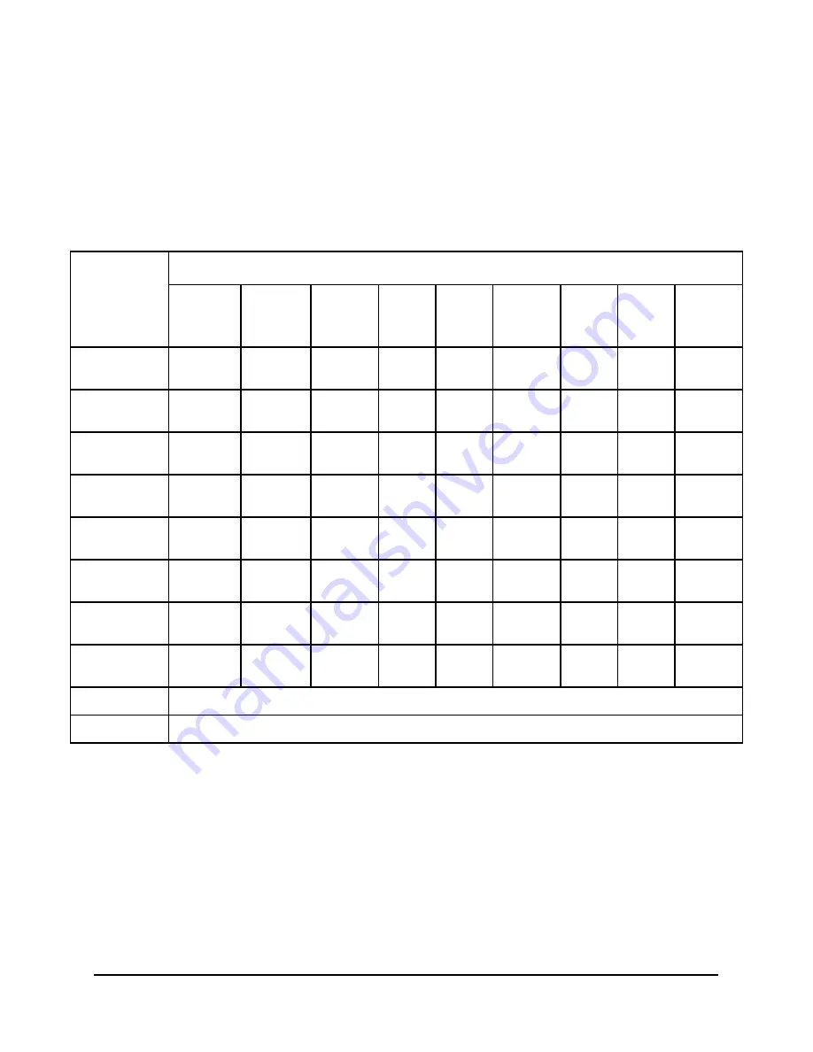
1.8.1 PLL Configuration
The 603 PLL is configured by the PLL_CFG[0–3] signals. For a given SYSCLK (bus) frequency, the PLL
configuration signals set the internal CPU and VCO frequency of operation. The PLL configuration for the
603 is shown in Table 11 for nominal frequencies.
Table 11. PowerPC 603 Microprocessor PLL Configuration
PLL_CFG[0–3]
CPU Frequency in MHz (VCO Frequency in MHz)
Bus-to-
Core
Multiplier
Core-to-
VCO
Multiplier
Bus
16.6 MHz
Bus
20 MHz
Bus
25 MHz
Bus
33.3 MHz
Bus
40 MHz
Bus
50 MHz
Bus
66.6 MHz
0000
1x
2x
—
—
—
—
—
—
66.6
(133)
0001
1x
4x
—
—
—
33.3
(133)
40
(160)
50
(200)
—
0010
1x
8x
16.6
(133)
20
(160)
25
(200)
—
—
—
—
0100
2x
2x
—
—
—
66.6
(133)
80
(160)
—
—
0101
2x
4x
33.3
(133)
40
(160)
50
(200)
—
—
—
—
1000
3x
2x
—
60
(120)
75
(150)
—
—
—
—
1001
3x
4x
50
(200)
60
(240)
—
—
—
—
—
1100
4x
2x
66.6
(133)
80
(160)
—
—
—
—
—
0011
PLL bypass
1111
Clock off
Notes:
1. The sample bus-to-core frequencies shown are for reference only.
2. Some PLL configurations may select bus, CPU, or PLL frequencies which are not supported by the 603; see
Section 1.4.2.2, “Input AC Specifications,” for valid SYSCLK frequencies.
3. In PLL-bypass mode, the SYSCLK input signal clocks the internal processor directly, the PLL is disabled, and the bus
mode is set for 1:1 mode operation. This mode is intended for factory use only. Note: The AC timing specifications
given in this document do not apply in PLL-bypass mode.
4. In clock-off mode, no clocking occurs inside the 603 regardless of the SYSCLK input.
5. PLL_CFG[0–1] signals select the CPU-to-bus ratio (1:1, 2:1, 3:1, 4:1), PLL_CFG[2–3] signals select the CPU-to-PLL
multiplier (x2, x4, x8).


