


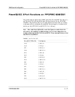
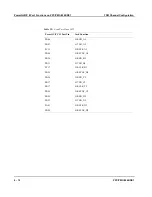


TDM Channel Configuration
Routing Time Division Multiplex Timeslots
PPC/PMC-8260/DS1
6 - 9
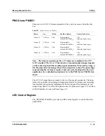
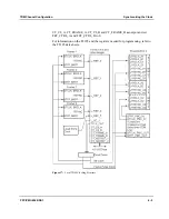
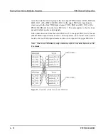
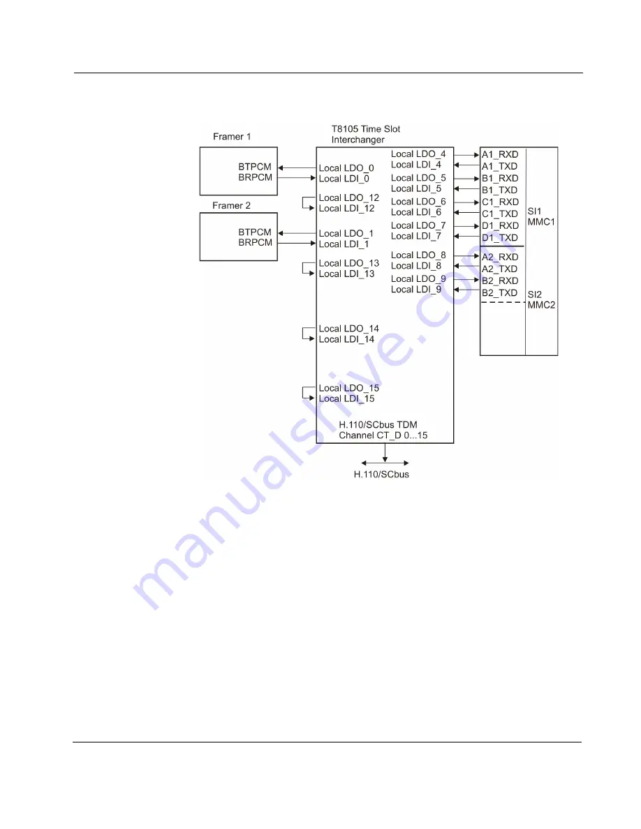
Figure 20:
Connection of Local TDM Streams
When using the H.110-F variant together with a PPC/PowerCoreCPCI-6750 Rev.
2.x or an MFIO-120, additional data lines are provided via the inter-TDM link.
The reason is that the capacitive load restriction of the H.110 bus allows to connect
only PMC slot 2 to the H.110 backplane bus connector P4. Therefore, PPC/PMC-
8260/DS1 modules mounted in PMC slot 1 of the reference CompactPCI carrier
boards do not have a physical H.110 bus connection.
To allow sharing and exchanging TDM streams between the two PMC slots, the
Motorola reference CompactPCI carrier boards CPCI-6750 Rev. 2.x and MFIO-
120 implement an on-board inter-TDM link connection. This link is a simple cross-
connection of four TDM streams and one TDM clock signal and one frame pulse
signal.
Summary of Contents for PPC/PMC-8260/DS1
Page 1: ...PPC PMC 8260 DS1 Reference Guide P N 6806800B10A July 2006 ...
Page 8: ...viii PPC PMC 8260 DS1 ...
Page 22: ...xxii PPC PMC 8260 DS1 ...
Page 26: ...xxvi PPC PMC 8260 DS1 ...
Page 30: ...xxx PPC PMC 8260 DS1 ...
Page 31: ...1 Introduction ...
Page 32: ......
Page 39: ...2 Installation ...
Page 40: ......
Page 53: ...3 Indicators and Connectors ...
Page 54: ......
Page 64: ...On Board Connectors Indicators and Connectors 3 12 PPC PMC 8260 DS1 ...
Page 65: ...4 Firmware ...
Page 66: ......
Page 104: ...Code Examples Firmware 4 40 PPC PMC 8260 DS1 ...
Page 105: ...5 Memory Map and Devices ...
Page 106: ......
Page 132: ...Resetting the Devices Memory Map and Devices 5 28 PPC PMC 8260 DS1 ...
Page 133: ...6 TDM Channel Configuration ...
Page 134: ......
Page 145: ...A Troubleshooting ...
Page 146: ......
Page 148: ...A 4 PPC PMC 8260 DS1 ...
Page 150: ...I 2 PPC PMC 8260 DS1 ...