

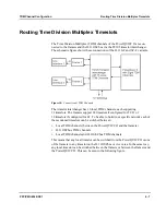


TDM Channel Configuration
PowerQUICC II Port Functions on PPC/PMC-8260/DS1
PPC/PMC-8260/DS1
6 - 11
PowerQUICC II Port Functions on PPC/PMC-8260/DS1
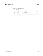
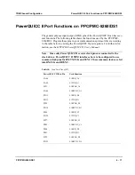
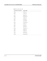
The general purpose input/output (GPIO) pins of the PowerQUICC II can have sev-
eral functions. The following table shows the functions used by the PPC/PMC-
8260/DS1. Program these pins in your communications protocol driver according
to the table below by setting the PowerQUICC II port registers. For further infor-
mation, see the
MPC8260 PowerQUICC II User’s Manual
.
Note: Since only PowerQUICC II receive clock pins are connected to the
clock driver, PowerQUICC II TDM interfaces have to be configured to use
common clock pins for RX/TX CLK and SYNC. These common clocks are fed
into RXCLK and RSYNC.
Table 38:
Used Port Pins of SI1
PowerQUICC II Port Pin
Used Function
PA08
L1RXD_A1
PA09
L1TXD_A1
PC31
L1RCLK_A1
PA06
L1RSYNC_A1
PD12
L1RXD_B1
PD13
L1TXD_B1
PC29
L1RCLK_B1
PD10
L1RSYNC_B1
PB14
L1RXD_C1
PD28
L1TXD_C1
PC27
L1RCLK_C1
PB12
L1RSYNC_C1
PB10
L1RXD_D1
PB11
L1TXD_D1
PC25
L1RCLK_D1
PD23
L1RSYNC_D1
Summary of Contents for PPC/PMC-8260/DS1
Page 1: ...PPC PMC 8260 DS1 Reference Guide P N 6806800B10A July 2006 ...
Page 8: ...viii PPC PMC 8260 DS1 ...
Page 22: ...xxii PPC PMC 8260 DS1 ...
Page 26: ...xxvi PPC PMC 8260 DS1 ...
Page 30: ...xxx PPC PMC 8260 DS1 ...
Page 31: ...1 Introduction ...
Page 32: ......
Page 39: ...2 Installation ...
Page 40: ......
Page 53: ...3 Indicators and Connectors ...
Page 54: ......
Page 64: ...On Board Connectors Indicators and Connectors 3 12 PPC PMC 8260 DS1 ...
Page 65: ...4 Firmware ...
Page 66: ......
Page 104: ...Code Examples Firmware 4 40 PPC PMC 8260 DS1 ...
Page 105: ...5 Memory Map and Devices ...
Page 106: ......
Page 132: ...Resetting the Devices Memory Map and Devices 5 28 PPC PMC 8260 DS1 ...
Page 133: ...6 TDM Channel Configuration ...
Page 134: ......
Page 145: ...A Troubleshooting ...
Page 146: ......
Page 148: ...A 4 PPC PMC 8260 DS1 ...
Page 150: ...I 2 PPC PMC 8260 DS1 ...


