


PPC/PMC-8260/DS1
A - 3
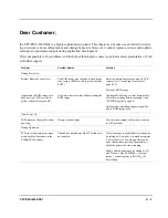
Dear Customer,
the PPC/PMC-8260/DS1 is a highly sophisticated product. This chapter can be taken as a hint list for detect-
ing erroneous system configurations and strange behaviors. However, it cannot replace a serious and sophisti-
cated pre and post sales support during application development.
If it is not possible to fix a problem with the help of this chapter, contact your local sales representative or FAE
for further support.
Problem
Possible Reason
Solution
During Power Up
Primary Booter does not start
The ROM image area in the boot flash device
is not empty (LEDs switch to green/off after
POST).
Enforce primary booter execution via PCR
register (see “Controlling Boot Process”
page 4-13).
Erase the ROM image
Application in ROM image area
does not start / LEDs switch to
yellow/yellow after green/off.
A software reset occured while executing the
ROM image.
Configure ROM image so that firmware dis-
ables the watchdog before executing it (see
“SYPCR Register” page 4-9).
Add software watchdog support to applica-
tion in ROM image area.
After Power Up
LEDs remain yellow/yellow after
power-up
Wrong switch settings
Verify switch settings (all switches must be
in OFF position).
During Operation
PCI error when trying to commu-
nicate with the firmware via the
4 MByte PCI window
The address translation of the PCI window is
not enabled.
Allow firmware to enable address translation
by setting bit 3 (value 8
16
) in mailbox register
6 (offset 468
16
) of PowerSpan. This can be
done either before resetting the module or
while the primary booter is running.
Enable address translation by setting bits 31
and 30 (hex. value C0000000
16
) in target
image 1 control register (offset 100
16
) of
PowerSpan.
Summary of Contents for PPC/PMC-8260/DS1
Page 1: ...PPC PMC 8260 DS1 Reference Guide P N 6806800B10A July 2006 ...
Page 8: ...viii PPC PMC 8260 DS1 ...
Page 22: ...xxii PPC PMC 8260 DS1 ...
Page 26: ...xxvi PPC PMC 8260 DS1 ...
Page 30: ...xxx PPC PMC 8260 DS1 ...
Page 31: ...1 Introduction ...
Page 32: ......
Page 39: ...2 Installation ...
Page 40: ......
Page 53: ...3 Indicators and Connectors ...
Page 54: ......
Page 64: ...On Board Connectors Indicators and Connectors 3 12 PPC PMC 8260 DS1 ...
Page 65: ...4 Firmware ...
Page 66: ......
Page 104: ...Code Examples Firmware 4 40 PPC PMC 8260 DS1 ...
Page 105: ...5 Memory Map and Devices ...
Page 106: ......
Page 132: ...Resetting the Devices Memory Map and Devices 5 28 PPC PMC 8260 DS1 ...
Page 133: ...6 TDM Channel Configuration ...
Page 134: ......
Page 145: ...A Troubleshooting ...
Page 146: ......
Page 148: ...A 4 PPC PMC 8260 DS1 ...
Page 150: ...I 2 PPC PMC 8260 DS1 ...


