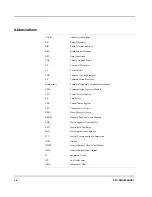


xxviii
PPC/PMC-8260/DS1
Installation
Es dürfen nur bestimmte Varianten des PPC/PMC-8260/DS1 kombiniert
werden (siehe Abschnitt “Allowed Product Combinations” auf Seite 2-8).
Sonst können das PMC Modul oder die Trägerkarte beschädigt werden.
Das PPC/PMC-8260/DS1 ist nicht für den Betrieb mit einer TNV-1 Spannung
(Telecommunication Network Voltage-1 Spannung) zertifiziert. Verbinden Sie
E1/T1/J1 nicht direkt mit der TNV-1 Spannung. Verwenden Sie eine Digital
Service Unit/Control Service Unit (DSU/CSU), um Überspannungen zu ver-
meiden.
Elektrostatische Entladung und unsachgemäßer Ein- und Ausbau des PMC
Moduls kann Schaltkreise beschädigen oder ihre Lebensdauer verkürzen.
Beachten Sie deshalb die folgenden Punkte:
•
Lesen Sie vor Ein- oder Ausbau des PMC Moduls das Kapitel “Installa-
tion” und das Installationshandbuch der betreffenden Trägerkarte.
•
Führen Sie vor Ein- und Ausbau des PMC Moduls auf eine oder von einer
CompactPCI oder VME Trägerkarte, die kein Hot Swap unterstützt, fol-
gende Schritte durch:
– Prüfen Sie, welche Schritte bei den bereits im System installierten
Boards vor dem Abschalten des Stroms durchgeführt werden müssen.
– Führen Sie die Schritte aus.
– Schalten Sie den Strom ab.
•
Ist mehr als ein PPC/PMC-8260/DS1 auf einem VME Board installiert, so
kann dies zu einer Überlastung des Konverters führen, der die 3,3 Volt
Spannungsversorgung auf dem VME Board generiert, und das Board
wird beschädigt. Stellen Sie deshalb sicher, daß die 3,3 Volt Versorgung des
VME Boards die in Table 4 “Current and Power Requirements” on page
2-6 beschriebenen Anforderungen einhält.
•
Die PMC Spezifikation (P1386.1) sieht eine maximale Leistungsaufnahme
von 7,5W für jedes PMC Modul vor. In der Standardkonfiguration kann
das PPC/PMC-8260/DS1 diesen Wert überschreiten. Es ist deshalb not-
wendig, die Stromversorgung der Trägerkarte mit den Anforderungen des
PPC/PMC-8260/DS1 abzustimmen. Aufgrund der hohen Leistung-
saufnahme ist eine Zwangskühlung notwendig (siehe Tabelle 6 “Environ-
mental Requirements of the PMC-8260/DS1” auf Seite 2-10).
•
Bevor Sie Boards oder elektronische Komponenten berühren, vergewis-
sern Sie sich, dass Sie in einem ESD-geschützten Bereich arbeiten.
•
Stellen Sie sicher, dass die 3.3V and 5V Stromversorgungseinheiten auf der
Trägerkarte gleichzeitig in höchstens 20 msec. betriebsbereit sind. Anson-
sten wird das PMC Modul beschädigt.
Summary of Contents for PPC/PMC-8260/DS1
Page 1: ...PPC PMC 8260 DS1 Reference Guide P N 6806800B10A July 2006 ...
Page 8: ...viii PPC PMC 8260 DS1 ...
Page 22: ...xxii PPC PMC 8260 DS1 ...
Page 26: ...xxvi PPC PMC 8260 DS1 ...
Page 30: ...xxx PPC PMC 8260 DS1 ...
Page 31: ...1 Introduction ...
Page 32: ......
Page 39: ...2 Installation ...
Page 40: ......
Page 53: ...3 Indicators and Connectors ...
Page 54: ......
Page 64: ...On Board Connectors Indicators and Connectors 3 12 PPC PMC 8260 DS1 ...
Page 65: ...4 Firmware ...
Page 66: ......
Page 104: ...Code Examples Firmware 4 40 PPC PMC 8260 DS1 ...
Page 105: ...5 Memory Map and Devices ...
Page 106: ......
Page 132: ...Resetting the Devices Memory Map and Devices 5 28 PPC PMC 8260 DS1 ...
Page 133: ...6 TDM Channel Configuration ...
Page 134: ......
Page 145: ...A Troubleshooting ...
Page 146: ......
Page 148: ...A 4 PPC PMC 8260 DS1 ...
Page 150: ...I 2 PPC PMC 8260 DS1 ...


