


Installation
Switch Settings
PPC/PMC-8260/DS1
2 - 7
Switch Settings
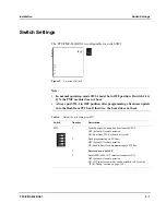
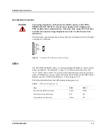
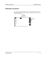
The PPC/PMC-8260/DS1 is configurable via switch SW1.
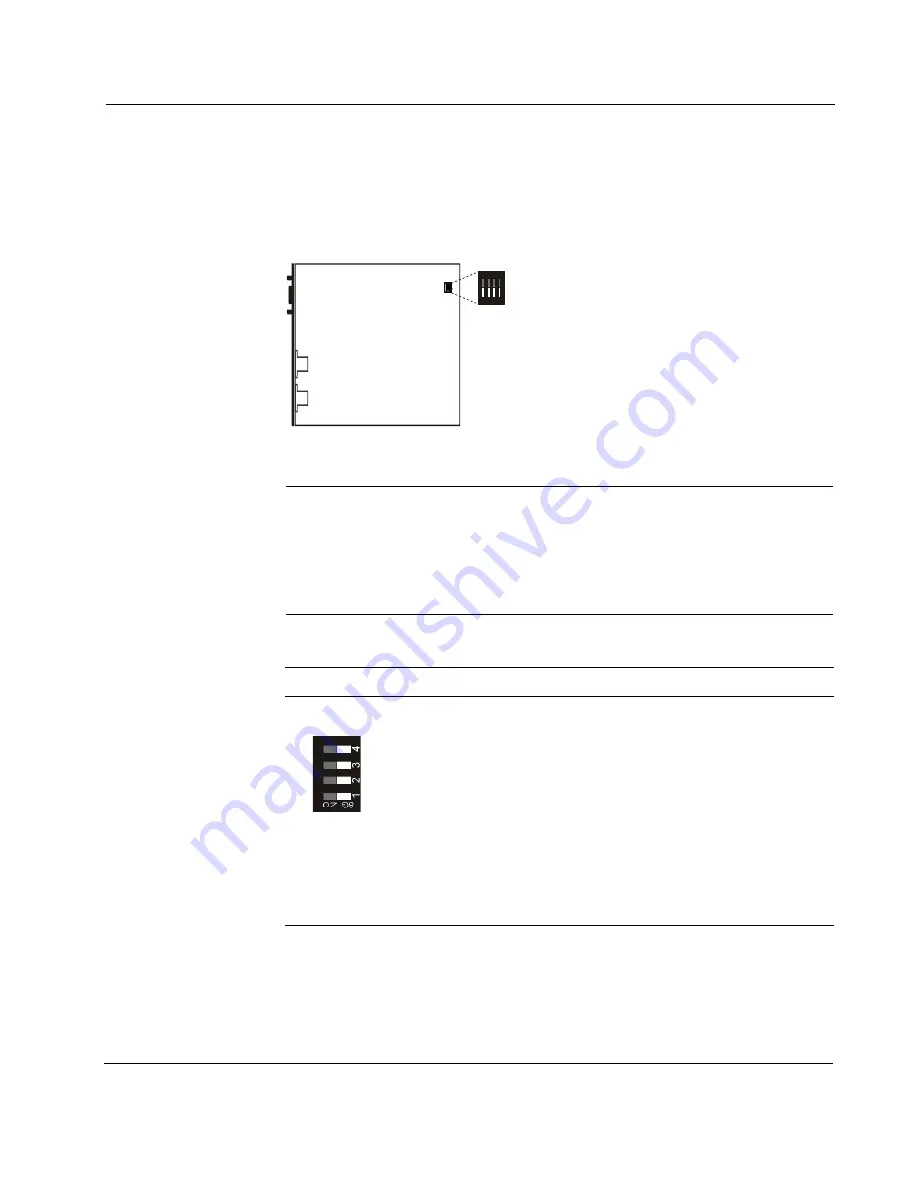
SW1
O
N
1 2 3 4
Figure 2:
Location of Switch
Note:
•
In normal operation mode SW1-1 must be in OFF position. If switch 1-1 is
ON, the PMC module does not boot.
•
Always put SW1-2 in OFF position after programming a firmware update
into the flash from PCI bus. Otherwise, the board does not boot.
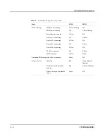
Table 5:
Default Switch Settings for SW1
Switch
Number
Description
SW1
1
PowerSpan power-up option boot from 60x/PCI:
OFF (default): Normal operation
ON: Boot from PCI (Lockout bit cleared)
2
Flash programming via PCI bus:
OFF (default): Normal operation
ON: Enable boot Flash programming via PCI bus
3
Reserved, must be OFF
4
Enable MPC8260 COP interface (connector P4)
OFF (default): Normal operation
ON: COP interface emulator can be attached to P4 (see the
“JTAG/Debug” section on page 3-10)
Summary of Contents for PPC/PMC-8260/DS1
Page 1: ...PPC PMC 8260 DS1 Reference Guide P N 6806800B10A July 2006 ...
Page 8: ...viii PPC PMC 8260 DS1 ...
Page 22: ...xxii PPC PMC 8260 DS1 ...
Page 26: ...xxvi PPC PMC 8260 DS1 ...
Page 30: ...xxx PPC PMC 8260 DS1 ...
Page 31: ...1 Introduction ...
Page 32: ......
Page 39: ...2 Installation ...
Page 40: ......
Page 53: ...3 Indicators and Connectors ...
Page 54: ......
Page 64: ...On Board Connectors Indicators and Connectors 3 12 PPC PMC 8260 DS1 ...
Page 65: ...4 Firmware ...
Page 66: ......
Page 104: ...Code Examples Firmware 4 40 PPC PMC 8260 DS1 ...
Page 105: ...5 Memory Map and Devices ...
Page 106: ......
Page 132: ...Resetting the Devices Memory Map and Devices 5 28 PPC PMC 8260 DS1 ...
Page 133: ...6 TDM Channel Configuration ...
Page 134: ......
Page 145: ...A Troubleshooting ...
Page 146: ......
Page 148: ...A 4 PPC PMC 8260 DS1 ...
Page 150: ...I 2 PPC PMC 8260 DS1 ...


