

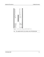


Indicators and Connectors
PPC/PMC-8260/DS1
3 - 5
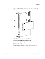
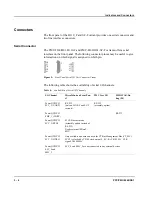
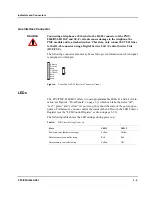
Line Interface Connector
Caution
Connecting a telephone or Ethernet to the RJ-45 connector of the PMC-
8260/DS1-H110-F and SC-F variants causes damage to the telephone, the
PMC module and to attached devices. Therefore, only connect E1/T1/J1 lines
to the RJ-45 connector using a Digital Service Unit / Control Service Unit
(DSU/CSU).
The following connector pinout may be useful to give information on which signal
is assigned to which pin.
1
2
3
4
5
6
7
8
1
8
Rx- (Ring/Input)
Rx+ (Tip/Input)
Reserved
Tx- (Ring/Output)
Tx+ (Tip/Output)
Reserved
Reserved
Reserved
Figure 6:
Front Panel RJ-45 Interface Connector Pinout
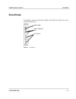
LEDs
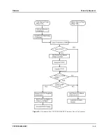
The PPC/PMC-8260/DS1 offers two user-programmable LEDs L1 and L2 (for lo-
cation see Figure 4 “Front Panels” on page 3-3) which can take the states “off”,
“red”, “green” and “yellow”. At power up, they show the state of the power-up se-
quence. Furthermore, you can control the status of the LEDs with the LED Control
Register (see the “LED Control Register” section on page 5-23).
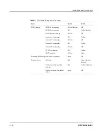
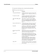
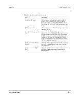
The following table shows the LED settings during power up:
Table 9:
LED States During Power Up
State
LED 1
LED 2
Power up/reset (hardware setting)
Yellow
Yellow
Before memory controller setup
Red
Red
After memory controller setup
Yellow
Off
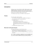
Summary of Contents for PPC/PMC-8260/DS1
Page 1: ...PPC PMC 8260 DS1 Reference Guide P N 6806800B10A July 2006 ...
Page 8: ...viii PPC PMC 8260 DS1 ...
Page 22: ...xxii PPC PMC 8260 DS1 ...
Page 26: ...xxvi PPC PMC 8260 DS1 ...
Page 30: ...xxx PPC PMC 8260 DS1 ...
Page 31: ...1 Introduction ...
Page 32: ......
Page 39: ...2 Installation ...
Page 40: ......
Page 53: ...3 Indicators and Connectors ...
Page 54: ......
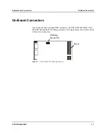
Page 64: ...On Board Connectors Indicators and Connectors 3 12 PPC PMC 8260 DS1 ...
Page 65: ...4 Firmware ...
Page 66: ......
Page 104: ...Code Examples Firmware 4 40 PPC PMC 8260 DS1 ...
Page 105: ...5 Memory Map and Devices ...
Page 106: ......
Page 132: ...Resetting the Devices Memory Map and Devices 5 28 PPC PMC 8260 DS1 ...
Page 133: ...6 TDM Channel Configuration ...
Page 134: ......
Page 145: ...A Troubleshooting ...
Page 146: ......
Page 148: ...A 4 PPC PMC 8260 DS1 ...
Page 150: ...I 2 PPC PMC 8260 DS1 ...


