


1
3
5
7
9
11
13
15
17
19
21
23
25
27
29
31
33
35
37
39
41
43
45
47
49
51
53
55
57
59
61
63
2
4
6
8
10
12
14
16
18
20
22
24
26
28
30
32
34
36
38
40
42
44
46
48
50
52
54
56
58
60
62
64
CT_MC
CT_D14
CT_D12
CT_D11
CT_D09
CT_D07
CT_D06
CT_D04
CT_D02
GND
CLKFAIL
CT_NETREF_1
GND
CT_FRAME_A
CT_FRAME_B
CT_C8_B
n.c.
n.c.
n.c.
n.c.
n.c.
n.c.
n.c.
BTCLK_PMC_OUT*
BTFP_PMC_OUT*
T8105_LDO<10>*
T8105_LDO<11>*
FET_CTRL_B
EARLY_PMC
T8105_LDI<10>*
T8105_LDI<11>*
n.c.
CT_D15
CT_D13
GND
CT_D10
CT_D08
GND
CT_D05
CT_D03
CT_D01
CT_D00
FR_COMP
SCLK
SCLKx2
FET_CTRL_A
CT_C8_A
CT_NETREF_2
BTCLK_PMC_IN*
BTFP_PMC_IN*
PQ2_C2_L1RXD_IN*
PQ2_D2_L1RXD_IN*
n.c.
n.c.
PQ2_C2_L1TXD_OUT*
PQ2_D2_L1TXD_OUT*
n.c.
n.c.
n.c.
n.c.
n.c.
n.c.
n.c.
n.c.
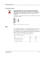
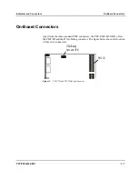
Indicators and Connectors
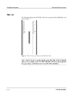
On-Board Connectors
PPC/PMC-8260/DS1
3 - 9
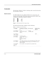
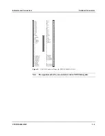
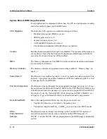
Figure 9:
PMC I/O Connector Pinout for PMC-8260/DS1-H110-F
Note: The signals marked by an asterisk are inter-TDM link signals.
Summary of Contents for PPC/PMC-8260/DS1
Page 1: ...PPC PMC 8260 DS1 Reference Guide P N 6806800B10A July 2006 ...
Page 8: ...viii PPC PMC 8260 DS1 ...
Page 22: ...xxii PPC PMC 8260 DS1 ...
Page 26: ...xxvi PPC PMC 8260 DS1 ...
Page 30: ...xxx PPC PMC 8260 DS1 ...
Page 31: ...1 Introduction ...
Page 32: ......
Page 39: ...2 Installation ...
Page 40: ......
Page 53: ...3 Indicators and Connectors ...
Page 54: ......
Page 64: ...On Board Connectors Indicators and Connectors 3 12 PPC PMC 8260 DS1 ...
Page 65: ...4 Firmware ...
Page 66: ......
Page 104: ...Code Examples Firmware 4 40 PPC PMC 8260 DS1 ...
Page 105: ...5 Memory Map and Devices ...
Page 106: ......
Page 132: ...Resetting the Devices Memory Map and Devices 5 28 PPC PMC 8260 DS1 ...
Page 133: ...6 TDM Channel Configuration ...
Page 134: ......
Page 145: ...A Troubleshooting ...
Page 146: ......
Page 148: ...A 4 PPC PMC 8260 DS1 ...
Page 150: ...I 2 PPC PMC 8260 DS1 ...


