

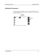


On-Board Connectors
Indicators and Connectors
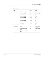
3 - 10
PPC/PMC-8260/DS1
JTAG/Debug
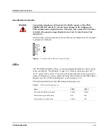
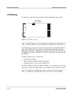
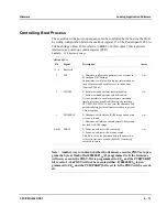
The following figure shows the location of the JTAG/Debug connector (P4).
JTAG/Debug
Connector (P4)
Figure 10:
JTAG/Debug Connector
Note: The COP interface is not available on revisions prior to Revision 1.2.
The JTAG/Debug connector provides the signals of the PowerQUICC II COP in-
terface port which allows easy connection of a Standard Motorola Third Party
COP-Interface Emulator. Additionally, it provides a second RS-232 interface for
debugging convenience (PowerQUICC II SMC1-interface) and the necessary sup-
ply voltages.
The COP-interface port can be used for:
•
Program flow tracking
•
Internal watch point and breakpoint generation
•
Emulation system control over PowerQUICC II
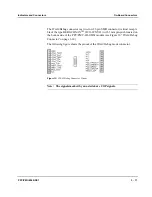
The RXD/TXD pins of the PowerQUICC II SMC_1 are connected to the develop-
ment port as well as the debug mode connector (Pins 8 and 9) via RS-232 drivers.
Note: To enable the COP interface, SW1-4 must be set to ON position.
Summary of Contents for PPC/PMC-8260/DS1
Page 1: ...PPC PMC 8260 DS1 Reference Guide P N 6806800B10A July 2006 ...
Page 8: ...viii PPC PMC 8260 DS1 ...
Page 22: ...xxii PPC PMC 8260 DS1 ...
Page 26: ...xxvi PPC PMC 8260 DS1 ...
Page 30: ...xxx PPC PMC 8260 DS1 ...
Page 31: ...1 Introduction ...
Page 32: ......
Page 39: ...2 Installation ...
Page 40: ......
Page 53: ...3 Indicators and Connectors ...
Page 54: ......
Page 64: ...On Board Connectors Indicators and Connectors 3 12 PPC PMC 8260 DS1 ...
Page 65: ...4 Firmware ...
Page 66: ......
Page 104: ...Code Examples Firmware 4 40 PPC PMC 8260 DS1 ...
Page 105: ...5 Memory Map and Devices ...
Page 106: ......
Page 132: ...Resetting the Devices Memory Map and Devices 5 28 PPC PMC 8260 DS1 ...
Page 133: ...6 TDM Channel Configuration ...
Page 134: ......
Page 145: ...A Troubleshooting ...
Page 146: ......
Page 148: ...A 4 PPC PMC 8260 DS1 ...
Page 150: ...I 2 PPC PMC 8260 DS1 ...


