


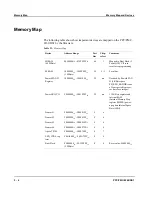


Memory Map and Devices
PowerSPAN II PCI Bus Bridge
PPC/PMC-8260/DS1
5 - 11
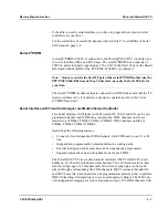
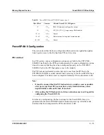
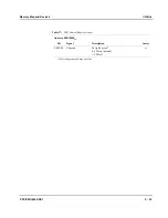
PowerSPAN II Configuration
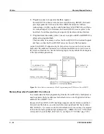
This section describes the basic configuration that needs to be applied by applica-
tions to gain access to the 60x bus from PCI and vice versa.
PCI Lockout
In a PCI system various configuration options are set both by the PPC/PMC-
8260/DS1 itself and by the PCI host independently. For some configuration options
it must be ensured that they have been configured properly on the PPC/PMC-
8260/DS1 before the PCI host gains access to the module.
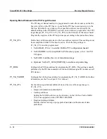
The PCI lockout mechanism ensures that any access from the PCI bus to the
PPC/PMC-8260/DS1 is retried until all basic resources of the PowerSPAN II have
been configured. The data access is completed normally if the lockout state is left.
Note:
•
It must be ensured that the PCI lockout state is ended as soon as possible
after power up. Most PCI systems have a retry limit which may cause
unpredictable results on the host, if reached.
•
After ending the PCI lockout state, it does not make sense to set it again for
configuring the PowerSPAN II.
In its factory configuration, the basic settings for the PowerSPAN II are pro-
grammed into the serial E
2
PROM which is loaded at power up. After the serial
download has been completed, the PCI lockout state is left.
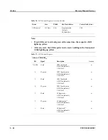
17
FF
16
IDR: All interrupts configured as output
18
00
16
PCI_I2O_CTL: I
2
O target image BAR disabled
19...31
00
16
Unused
32...63
00
16
Data elements for long load format (unused)
64...255
00
16
Unused
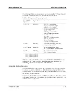
Table 25:
PowerSPAN II Serial E
2
PROM Contents (cont.)
Byte Offset
Contents
Affected PowerSPAN II Registers
Summary of Contents for PPC/PMC-8260/DS1
Page 1: ...PPC PMC 8260 DS1 Reference Guide P N 6806800B10A July 2006 ...
Page 8: ...viii PPC PMC 8260 DS1 ...
Page 22: ...xxii PPC PMC 8260 DS1 ...
Page 26: ...xxvi PPC PMC 8260 DS1 ...
Page 30: ...xxx PPC PMC 8260 DS1 ...
Page 31: ...1 Introduction ...
Page 32: ......
Page 39: ...2 Installation ...
Page 40: ......
Page 53: ...3 Indicators and Connectors ...
Page 54: ......
Page 64: ...On Board Connectors Indicators and Connectors 3 12 PPC PMC 8260 DS1 ...
Page 65: ...4 Firmware ...
Page 66: ......
Page 104: ...Code Examples Firmware 4 40 PPC PMC 8260 DS1 ...
Page 105: ...5 Memory Map and Devices ...
Page 106: ......
Page 132: ...Resetting the Devices Memory Map and Devices 5 28 PPC PMC 8260 DS1 ...
Page 133: ...6 TDM Channel Configuration ...
Page 134: ......
Page 145: ...A Troubleshooting ...
Page 146: ......
Page 148: ...A 4 PPC PMC 8260 DS1 ...
Page 150: ...I 2 PPC PMC 8260 DS1 ...


