


Installation
Requirements
PPC/PMC-8260/DS1
2 - 5
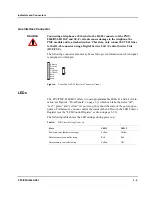
Note: To ensure that the operating conditions are met, forced air cooling is
required within the chassis environment.
Caution
Do not operate the product outside the specified environmental limits. High
humidity and condensation may cause short circuits. Make sure the product is
completely dry and there is no condensation of water on any parts of the
board’s surface before applying power. Do not operate the product below 0°C.
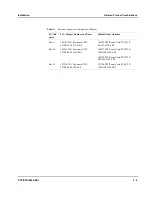
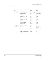
Table 3:
Environmental Requirements of the PPC/PMC-8260/DS1
Feature
Operating
Non-Operating
Temperature
0°C to +55°C
- 40°C to +85°C
Temp. Change
+/-0.5°C per minute
+/-1.0°C per minute
Forced Airflow
300 LFM (linear feet per minute)
-
Rel. Humidity
5% to 95% at +40°C
5% to 95% at +40°C
Altitude
-300 m to +3,000 m
-300 m to +13,000 m
Vibration
10 to 15 Hz
15 to 150 Hz
2 mm amplitude
2 g
5 mm amplitude
5 g
Shock
5 g/11 ms halfsine
15 g/11 ms halfsine
Free Fall
100 mm/3 axis
1200 mm/all edges and corners
(packed state)
Power Requirements
The power supply must meet the power requirements of the carrier board and the
PPC/PMC-8260/DS1 module. For the power requirements of the carrier board refer
to the respective Installation Guide.
Caution
•
The PMC module carrier board must guarantee that the 3.3V and 5V
power supplies ramp up simultaneously in about max. 20 msec. Otherwise,
the PMC module may be damaged.
•
The power supply circuits on VMEbus carrier boards may be overloaded
if more than one PPC/PMC-8260/DS1 is assembled. This results in perma-
nent damage to the carrier board. Therefore, make sure that the VMEbus
carrier board’s +3.3 Volt supply supports the power requirements
described in this section.
Summary of Contents for PPC/PMC-8260/DS1
Page 1: ...PPC PMC 8260 DS1 Reference Guide P N 6806800B10A July 2006 ...
Page 8: ...viii PPC PMC 8260 DS1 ...
Page 22: ...xxii PPC PMC 8260 DS1 ...
Page 26: ...xxvi PPC PMC 8260 DS1 ...
Page 30: ...xxx PPC PMC 8260 DS1 ...
Page 31: ...1 Introduction ...
Page 32: ......
Page 39: ...2 Installation ...
Page 40: ......
Page 53: ...3 Indicators and Connectors ...
Page 54: ......
Page 64: ...On Board Connectors Indicators and Connectors 3 12 PPC PMC 8260 DS1 ...
Page 65: ...4 Firmware ...
Page 66: ......
Page 104: ...Code Examples Firmware 4 40 PPC PMC 8260 DS1 ...
Page 105: ...5 Memory Map and Devices ...
Page 106: ......
Page 132: ...Resetting the Devices Memory Map and Devices 5 28 PPC PMC 8260 DS1 ...
Page 133: ...6 TDM Channel Configuration ...
Page 134: ......
Page 145: ...A Troubleshooting ...
Page 146: ......
Page 148: ...A 4 PPC PMC 8260 DS1 ...
Page 150: ...I 2 PPC PMC 8260 DS1 ...


