


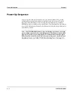


Power-Up Sequence
Firmware
4 - 6
PPC/PMC-8260/DS1
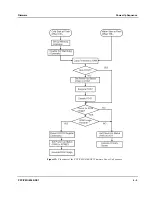
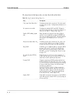
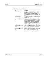
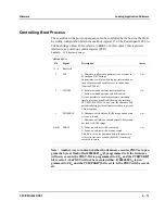
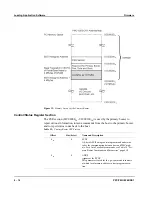
The steps shown in the figure above are described in the table below.
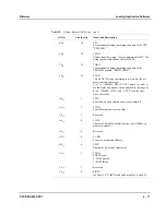
Table 10:
Steps Performed During Power-Up
Step
Description
Cold start at flash offset 100
16
The firmware starts code execution at 100
16
after a hard-
ware power up or a reset. At this point the hardware is not
initialized.
Set up memory controller
The firmware initializes the PowerQUICC II memory
controller and maps the devices to the local addresses as
shown in see Table 22 “Memory Map” page 5-4.
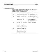
Disable SW Watchdog (option-
ally)
When the firmware starts execution, the watchdog is
enabled. It can be disabled by setting the WDDIS bit in
the power-up control register (PCR). For further informa-
tion, see the “Controlling Boot Process” section on
page 4-13.
Warm start at flash offset 108
16
The firmware starts code execution at 108
16
after a soft-
ware reset. Since the hardware was already initialized
after the cold start, the previous two steps are omitted.
Skip POST?
The POST can be enabled/disabled by setting the PSKIP
bit in the PCR register. Another way to influence the
POST execution is to program the byte at flash offset
000400F1
16
(see the “Controlling Boot Process” section
Set power-up status (PSR) to
POST
Before the power-on self-test is started, the value 1 is
written into the power-up status register (PSR). This sta-
tus bit can be used to poll the power-up status.
Execute POST
The power-on self-test (POST) provides basic tests for
SSRAM, SDRAM, PCI bridge and the I/O devices (fram-
ers, H.110 interface). The tests ensure proper connectivity
of devices on the board. However, no extensive func-
tional tests are performed.
Since the POST does not halt if it detects errors your
application software should evaluate the POST results
written into mailbox register 5 of the PowerSpan II as
soon as possible (see the “Obtaining Results from the
Power-On Self-Test” section on page 4-24).
Disable POST
If the POST is completed, the firmware sets the PSKIP bit
in the PCR register so that the POST is not executed again
after a warm start.
Summary of Contents for PPC/PMC-8260/DS1
Page 1: ...PPC PMC 8260 DS1 Reference Guide P N 6806800B10A July 2006 ...
Page 8: ...viii PPC PMC 8260 DS1 ...
Page 22: ...xxii PPC PMC 8260 DS1 ...
Page 26: ...xxvi PPC PMC 8260 DS1 ...
Page 30: ...xxx PPC PMC 8260 DS1 ...
Page 31: ...1 Introduction ...
Page 32: ......
Page 39: ...2 Installation ...
Page 40: ......
Page 53: ...3 Indicators and Connectors ...
Page 54: ......
Page 64: ...On Board Connectors Indicators and Connectors 3 12 PPC PMC 8260 DS1 ...
Page 65: ...4 Firmware ...
Page 66: ......
Page 104: ...Code Examples Firmware 4 40 PPC PMC 8260 DS1 ...
Page 105: ...5 Memory Map and Devices ...
Page 106: ......
Page 132: ...Resetting the Devices Memory Map and Devices 5 28 PPC PMC 8260 DS1 ...
Page 133: ...6 TDM Channel Configuration ...
Page 134: ......
Page 145: ...A Troubleshooting ...
Page 146: ......
Page 148: ...A 4 PPC PMC 8260 DS1 ...
Page 150: ...I 2 PPC PMC 8260 DS1 ...


