background image

User Guide: PTP 600 Series 

Wireless specifications 


phn-0896_012v000 


Jul 2010 


4-55


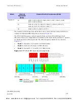
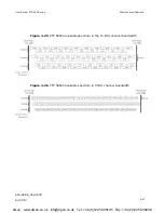
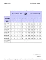
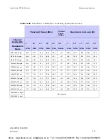
Figure 4-21  PTP 54600 available spectrum in 10 MHz channel bandwidth 


Figure 4-22  PTP 54600 available spectrum in 5 MHz channel bandwidth 


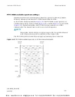
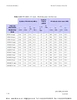
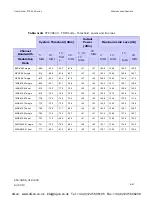
PTP 58600 available spectrum settings 

Adjustment of the lower centre frequency allows the operator to slide the available 
frequency settings up and down the 5.8 GHz band in steps of 2 MHz. 

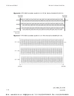
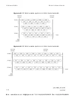
In the 30 MHz channel bandwidth (

Figure 4-23

), the PTP 58600 variant operates on a 

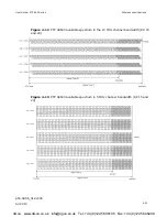
10 MHz channel raster. In the 15 MHz (

Figure 4-24

), 10 MHz (

Figure 4-25

) and 5 MHz 

(

Figure 4-26

) channel bandwidths, the PTP 58600 variant operates on a 6 MHz 

channel raster. The channel raster is set to even centre frequencies. 

NOTE


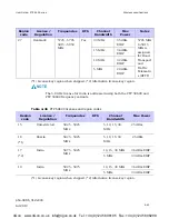
These tables contain data for one typical region code. The specified channel 
centre frequencies may not be available in other region codes. 

4Gon   www.4Gon.co.uk   info@4gon.co.uk   Tel: +44 (0)1245 808195   Fax: +44 (0)1245 808299 

Summary of Contents for PTP 600 Series

Page 1: ...PTP 600 Series phn 0896 012v000 User Guide System Release 600 09 01 2006 2010 Motorola Inc All Rights Reserved 4Gon www 4Gon co uk info 4gon co uk Tel 44 0 1245 808195 Fax 44 0 1245 808299 ...

Page 2: ...ed in the Motorola products described in this document may not be copied reproduced reverse engineered distributed merged or modified in any manner without the express written permission of Motorola Furthermore the purchase of Motorola products shall not be deemed to grant either directly or by implication estoppel or otherwise any license under the copyrights patents or patent applications of Mot...

Page 3: ...stall the equipment in accordance with national regulations In the USA follow Section 810 of the National Electric Code ANSI NFPA No 70 1984 USA In Canada follow Section 54 of the Canadian Electrical Code These codes describe correct installation procedures for grounding the outdoor unit mast lead in wire and discharge unit size of grounding conductors and connection requirements for grounding ele...

Page 4: ...untries for safe handling in wet conditions and therefore may create a safety hazard Non Motorola power supply Safety may be compromised if a different power supply is used than the one supplied by Motorola as part of the system Alternative DC supplies When using alternative DC supplies via the PIDU Plus DC in terminals such as battery backed DC power source the supply MUST comply with the followi...

Page 5: ...ective Ground in accordance with Local Electrical Regulations RF exposure near the antenna Strong radio frequency RF fields will be present close to the antenna when the transmitter is on Always mute the transmitter before undertaking maintenance activities in front of the antenna Minimum separation distances Install the ODUs so as to provide and maintain the minimum separation distances from all ...

Page 6: ...Safety phn 0896_012v000 iv Jul 2010 4Gon www 4Gon co uk info 4gon co uk Tel 44 0 1245 808195 Fax 44 0 1245 808299 ...

Page 7: ...mary disconnect device iii External cables iii Grounding PTP SYNC iii RF exposure near the antenna iii Minimum separation distances iii About This User Guide 1 Revision history 2 Version information 2 General information 3 Purpose 3 Cross references 3 Text conventions 4 Contacting Motorola 5 Feedback 5 Motorola Point to Point 5 Wireless Broadband Technical Support telephone numbers 5 Reporting pro...

Page 8: ...n 1 7 ODU interfaces 1 8 Connectorized ODU antenna interfaces 1 9 Mounting brackets 1 9 Network connection 1 10 Powered indoor unit PIDU Plus 1 11 PIDU Plus description 1 11 PIDU Plus interfaces 1 11 Redundancy and alternative powering configurations 1 13 Remote LEDs and recovery switch 1 15 PIDU Plus maximum cable lengths 1 15 Cabling and lightning protection 1 16 PTP and lightning protection 1 1...

Page 9: ...frequency selection 1 29 Radar avoidance 1 30 Security 1 31 Region codes 1 31 PTP networks 1 32 TDD synchronization 1 33 Ethernet bridging 1 36 Customer network 1 36 Management network 1 37 Back to back links 1 39 Protocol model 1 39 Telecoms circuits 1 41 Lowest telecoms modulation mode 1 41 Fixed frequency operation 1 41 Further reading 1 42 System management 1 43 Management agent 1 43 Web serve...

Page 10: ...ction 2 7 Wind loading 2 7 Link planning 2 10 Range and obstacles 2 10 PTP Link Planner 2 10 Using PTP Link Planner for synchronized networks 2 11 Path loss considerations 2 11 When to use the connectorized PTP 600 antennas 2 13 System threshold output power and link loss 2 13 Grounding and lightning protection 2 14 Standards 2 14 Lightning protection zones 2 14 General protection requirements 2 1...

Page 11: ...anagement mode 2 35 VLAN membership 2 35 Priority for management traffic 2 35 IP interface 2 36 Quality of service for bridged Ethernet traffic 2 36 Back to back links 2 36 Green Ethernet switches 2 36 Security planning 2 37 Planning for HTTPS TLS operation 2 37 Planning for FIPS 140 2 operation 2 38 Planning for SNMP operation 2 39 Planning for SNMPv3 operation 2 41 Chapter 3 Legal information 3 ...

Page 12: ...NC installations 4 8 Inventory for GPS receiver installations 4 9 Inventory for E1 or T1 installations 4 11 ODU specifications 4 12 Dimensions and weight 4 12 Environmental 4 13 PIDU Plus specifications 4 14 Dimensions and weight 4 14 Environmental 4 14 Electrical 4 15 Cable and connector specifications 4 16 Outdoor CAT5e cable drop cable 4 16 Outdoor connectors and glands ODU or LPU 4 16 Outdoor ...

Page 13: ...ACM default configuration 4 78 RADIUS protocols and attributes 4 79 Email alerts 4 81 Event notification messages 4 82 Safety compliance 4 89 Electrical safety compliance 4 89 Electromagnetic compliance 4 90 EMC immunity compliance 4 90 Radio certifications 4 91 Compliance with regulations 4 91 Regulatory issues with connectorized units 4 94 Electromagnetic energy 4 98 Examples of regulatory limit...

Page 14: ...oist the ODU 5 15 Mounting the ODU and top LPU 5 16 Installing the drop cable and ground cables 5 18 Connecting the ODU to the top LPU 5 19 Installing and grounding the drop cable on a mast 5 20 Installing and grounding the drop cable at building entry 5 22 Installing the PIDU Plus 5 24 Mounting the PIDU Plus 5 24 Connecting the PIDU Plus to the ODU cable 5 24 Forming a drip loop 5 26 Preparing th...

Page 15: ...nting the LPU and connecting the GPS receiver 5 48 Installing an E1 or T1 interface 5 49 Preparing for E1 or T1 installation 5 49 Preparing the E1 or T1 drop cable 5 49 Installing the E1 or T1 top LPU 5 49 Connecting the ODU to the E1 or T1 top LPU 5 50 Installing the E1 or T1 drop and ground cables 5 50 Installing the E1 or T1 patch panel 5 51 Testing the E1 T1 installation 5 53 Chapter 6 Configu...

Page 16: ...ummary and status pages 6 45 Task 7 Configure wireless interface 6 46 Updating the system configuration 6 46 Updating quality of service 6 48 Updating wireless configuration 6 50 Configuring telecoms circuits 6 68 Task 8 Align antennas 6 71 Starting up the units 6 71 Using the graphical installation option 6 72 Using the ODU installation tones 6 73 Aligning the units 6 74 Observing behavior during...

Page 17: ...ment 7 2 Accessing the web interface 7 2 Menu navigation bar 7 3 Using the menu options 7 4 Viewing the system summary 7 6 Viewing the system status 7 11 Managing spectrum 7 22 Configuring spectrum usage at the master 7 22 Viewing spectrum usage at the slave 7 25 Interpreting the spectrum management plots 7 27 Viewing the active channel history 7 36 Viewing historic spectrum management metrics 7 3...

Page 18: ...f the drop cable 8 12 Test UltraSync GPS receiver 8 15 Test radio link 8 16 No activity 8 16 Some activity 8 17 Lightning strike 8 18 PTP SYNC fault finding guide 8 19 LEDs do not illuminate 8 19 The STATUS LED does not blink 8 19 The ODU LED does not illuminate within 90 seconds of power up 8 19 The GPS LED does not illuminate or blink on clustered PTP SYNC units 8 20 Using recovery mode 8 21 Ent...

Page 19: ...upply and redundant AC supply 1 14 Figure 1 13 Remote LED and recovery switch wiring 1 15 Figure 1 14 Cable grounding kit for 1 4 and 3 8 cable 1 17 Figure 1 15 LPU double end kit 1 18 Figure 1 16 LPU single end kit 1 19 Figure 1 17 PTP SYNC kit 1 20 Figure 1 18 PTP SYNC front panel 1 21 Figure 1 19 TDD cycle 1 24 Figure 1 20 Protocol layers between Ethernet and wireless interfaces 1 40 Figure 1 2...

Page 20: ...and lightning protection for GPS receiver on tower or mast 2 34 Figure 4 1 UltraSync unit 4 7 Figure 4 2 PTP 25600 BRS band channel assignments 4 45 Figure 4 3 PTP 45600 available spectrum in 30 MHz channel bandwidth RC 23 4 46 Figure 4 4 PTP 45600 available spectrum in 20 MHz channel bandwidth RC 23 4 47 Figure 4 5 PTP 45600 available spectrum in 15 MHz channel bandwidth RC 23 4 47 Figure 4 6 PTP...

Page 21: ...re 4 32 PTP 600 range adjustment for data rates curve B 4 130 Figure 4 33 PTP 600 range adjustment for data rates curve C 4 131 Figure 4 34 PTP 600 range adjustment for data rates curve D 4 131 Figure 4 35 PTP 600 range adjustment for data rates curve E 4 132 Figure 4 36 PTP 600 range adjustment for data rates curve F 4 132 Figure 4 37 PTP 600 range adjustment for data rates curve G 4 133 Figure 4...

Page 22: ...ble to telecoms channels T568B 5 51 Figure 5 26 Example of a Balun 5 52 Figure 6 1 IP configuration on the PC 6 3 Figure 6 2 Internet Protocol TCP IP Properties page 6 3 Figure 6 3 LAN Configuration page 6 6 Figure 6 4 LAN Configuration page with VLAN enabled 6 7 Figure 6 5 LAN Configuration page with auto negotiation disabled 6 7 Figure 6 6 Configuration Reboot page 6 11 Figure 6 7 Configuration ...

Page 23: ...nfiguration page with T1 enabled 6 52 Figure 6 34 Step 2 Wireless Configuration page 6 54 Figure 6 35 Step 2 Wireless Configuration page for connectorized ODUs 6 55 Figure 6 36 Step 2 Wireless Configuration page extract for fixed frequency 6 63 Figure 6 37 Step 3 TDD Synchronization page 6 64 Figure 6 38 Step 3 Confirm Installation Configuration page 6 67 Figure 6 39 Reboot confirmation pop up 6 6...

Page 24: ...ed 7 20 Figure 7 7 Status page TDD enabled and not synchronized 7 20 Figure 7 8 Spectrum Management as seen from the Master 7 23 Figure 7 9 Spectrum Management as seen from the Slave 7 26 Figure 7 10 Example spectrum management plot 7 27 Figure 7 11 Spectrum Management Fixed Frequency Mode page 7 30 Figure 7 12 Spectrum Management page with radar avoidance master 7 32 Figure 7 13 Spectrum Manageme...

Page 25: ...e 8 4 Drop cable tester front and back views 8 13 Figure 8 5 GPS synchronization unit 8 15 Figure 8 6 PIDU Plus recovery switch location 8 21 Figure 8 7 Recovery Image Warning page 8 22 Figure 8 8 Recovery Options page 8 22 4Gon www 4Gon co uk info 4gon co uk Tel 44 0 1245 808195 Fax 44 0 1245 808299 ...

Page 26: ...nts 4 5 Table 4 3 PTP SYNC installation components 4 8 Table 4 4 GPS receiver installation components 4 9 Table 4 5 Integrated ODU physical specifications 4 12 Table 4 6 Connectorized ODU physical specifications 4 12 Table 4 7 ODU environmental specifications 4 13 Table 4 8 PIDU Plus physical specifications 4 14 Table 4 9 PIDU Plus environmental specifications 4 14 Table 4 10 PIDU Plus electrical ...

Page 27: ...7 Table 4 33 PTP 49600 licenses and region codes 4 38 Table 4 34 PTP 54600 licenses and region codes 4 39 Table 4 35 PTP 58600 licenses and region codes 4 40 Table 4 36 PTP 59600 licenses and region codes 4 43 Table 4 37 PTP 25600 channel plan FCC BRS EBS Post Transition Band 4 44 Table 4 38 PTP 58600 band edge Tx power reduction 4 58 Table 4 39 PTP 25600 IP mode threshold power and link loss 4 62...

Page 28: ...ion messages 4 84 Table 4 65 Authentication configuration messages 4 84 Table 4 66 Telnet messages 4 85 Table 4 67 TFTP messages 4 85 Table 4 68 RADIUS messages 4 86 Table 4 69 Security configuration messages 4 86 Table 4 70 License key messages 4 88 Table 4 71 Management messages 4 88 Table 4 72 SNTP messages 4 88 Table 4 73 Low resource messages 4 88 Table 4 74 PTP 600 safety compliance specific...

Page 29: ... 8 Table 6 2 Capability summary attributes 6 13 Table 6 3 HTTP and Telnet attributes 6 33 Table 6 4 User account management attributes 6 38 Table 6 5 Password complexity configuration attributes 6 40 Table 6 6 Identity based user accounts attributes 6 43 Table 6 7 System Configuration attributes 6 46 Table 6 8 QoS default settings 6 49 Table 6 9 Step 1 Interface Configuration standard attributes 6...

Page 30: ... represented in the spectrum management plot radar avoidance 7 34 Table 7 10 Interference represented in the time series plot 7 37 Table 7 11 Setting tFTP attributes 7 38 Table 7 12 Monitoring tFTP attributes 7 39 Table 7 13 System Histograms attributes in the System Statistics page 7 43 Table 7 14 Data Port Counter attributes in the System Statistics page 7 45 Table 7 15 Management Port Counter a...

Page 31: ...s Ethernet Bridges It is intended for use by the link planner system installer and the end user IT professional The users of this guide will require expertise in the following areas Outdoor radio equipment installation Network configuration Use of web browser for system configuration monitoring and fault finding 4Gon www 4Gon co uk info 4gon co uk Tel 44 0 1245 808195 Fax 44 0 1245 808299 ...

Page 32: ... release 600 08 00 008v004 Apr 2009 System release 600 08 01 008v005 May 2009 System release 600 08 02 008v007 Jul 2009 System release 600 08 03 009v000 Nov 2009 System release 600 08 03 revised 010v000 Feb 2010 System release 600 08 04 011v000 Apr 2010 System release 600 08 50 012v000 Jul 2010 System release 600 09 01 4Gon www 4Gon co uk info 4gon co uk Tel 44 0 1245 808195 Fax 44 0 1245 808299 ...

Page 33: ...m performance arising directly or indirectly out of the failure of the customer or anyone acting on the customer s behalf to abide by the instructions system parameters or recommendations made in this document Cross references References to external publications are shown in italics Other cross references emphasized in blue text in electronic versions are active links to the references This docume...

Page 34: ...s utilities and environmental variables that appear on the screen are shown like this Special key sequences Special key sequences are represented as follows CTRL C Press the Ctrl and C keys at the same time CTRL SHIFT C Press the Ctrl Shift and C keys at the same time ALT F Press the Alt and F keys at the same time ALT SHIFT F11 Press the Alt Shift and F11 keys at the same time Press the pipe symb...

Page 35: ...la Inc 1303 E Algonquin Road Schaumburg Illinois 60196 U S A Web Site http www motorola com ptp Sales Enquiries sales ptp motorola com Web Support http www motorola com ptp support Email Support support ptp motorola com All Other Enquiries info ptp motorola com Wireless Broadband Technical Support telephone numbers Region and country Support telephone number North America USA and Canada 866 961 92...

Page 36: ...l 0217616160 Spain 912754787 Russia 810 800 228 41044 Saudi Arabia 800 844 5345 South Africa 0800981900 United Kingdom 0203 0277499 All other countries 44 203 0277499 Latin and Central America Argentina 0800 666 2789 Brazil 0800 891 4360 Chile 800 225 288 Columbia 01 800 912 0557 Mexico 001 800 942 7721 Peru 0800 70 086 All other countries 420 533 336 946 4Gon www 4Gon co uk info 4gon co uk Tel 44...

Page 37: ... at http www motorola com ptp 3 Ask for assistance from the Motorola product supplier 4 Gather information from affected units such as o The IP addresses and MAC addresses o The software releases o The configuration of software features o Any available diagnostic downloads 5 Escalate the problem to Motorola as follows o Either send e mail to support ptp motorola com o Or call Wireless Broadband Te...

Page 38: ... thirty 30 days of receipt of the defective product Repaired or replaced product will be subject to the original warranty period but not less than thirty 30 days To register PTP products or activate warranties visit http www motorola com ptp support For warranty assistance contact the reseller or distributor CAUTION Using non Motorola parts for repair could damage the equipment or void warranty Co...

Page 39: ...ered are protecting the confidentiality integrity and availability of information and assets Assets include the ability to communicate information about the nature of the communications and information about the parties involved In certain instances Motorola makes specific recommendations regarding security practices however the implementation of these recommendations and final responsibility for ...

Page 40: ...uence for not following the instructions in the warning Cautions Cautions precede instructions and are used when there is a possibility of damage to systems software or individual items of equipment within a system However this damage presents no danger to personnel A caution has the following format CAUTION Caution text and consequence for not following the instructions in the caution Notes A not...

Page 41: ...e Electrical and Electronic Equipment WEEE Do not dispose of Motorola equipment in landfill sites In the EU Motorola in conjunction with a recycling partner ensures that equipment is collected and recycled according to the requirements of EU environmental law Disposal of surplus packaging Do not dispose of surplus packaging in landfill sites In the EU it is the individual recipient s responsibilit...

Page 42: ...Caring for the environment phn 0896_012v000 12 Jul 2010 4Gon www 4Gon co uk info 4gon co uk Tel 44 0 1245 808195 Fax 44 0 1245 808299 ...

Page 43: ... main hardware components The following topics are described in this chapter Overview on page 1 2 Outdoor unit ODU on page 1 7 Powered indoor unit PIDU Plus on page 1 11 Cabling and lightning protection on page 1 16 PTP SYNC unit on page 1 20 Wireless operation on page 1 23 Ethernet bridging on page 1 36 Telecoms circuits on page 1 41 System management on page 1 43 FIPS 140 2 on page 1 56 4Gon www...

Page 44: ... Multiplexing OFDM modulation and Multiple Input Multiple Output MIMO techniques Wireless connections of up to 200km 124 miles in near line of sight conditions and up to 10km 6 miles in deep non line of sight conditions Coexistence with other users of the band using a combination of Automatic Transmit Power Control ATPC Spectrum Management functionality and Antenna beam shape High link availabilit...

Page 45: ...rence from nearby devices At initialization the PTP 600 Series monitors the available frequency channels to find a channel that is clear of interference In operation the PTP 600 Series continuously monitors the spectrum to ensure it is operating on the cleanest channel Typical deployment The PTP 600 Series Bridge consists of an identical pair of units deployed one at each end of the link The radio...

Page 46: ...cy variants are listed in Table 1 1 Table 1 1 PTP 600 Series frequency variants Variant Region Frequency Coverage Variable Channel Bandwidth Channel Raster 2496 2568 MHz 5 10 15 30 MHz 5 5 MHz 2572 2614 MHz 5 10 15 30 MHz 6 MHz PTP 25600 FCC BRS EBS Post Transition Band 2618 2690 MHz 5 10 15 30 MHz 5 5 MHz 4404 4596 MHz 5 10 15 20 MHz 6 MHz US Federal 4404 4596 MHz 30 MHz 10 MHz PTP 45600 NTIA 440...

Page 47: ...MHz 6 MHz PTP 58600 ETSI 5 GHz Band C FCC ISM Band 5725 5850 MHz 30 MHz 10 MHz 5 10 15 MHz 6 MHz Russia 5825 5925 MHz 30 MHz 10 MHz 5 10 15 MHz 6 MHz PTP 59600 India 5875 5925 MHz 30 MHz 10 MHz NOTE For PTP 25600 channel widths of 30 MHz are available where allowed by local regulations and subject to some restrictions on channel choice For PTP 58600 ETSI 5 GHz Band C use of the product is only all...

Page 48: ...ing all the radio and networking electronics PIDU Plus An indoor connection box containing a mains power supply status indicators and network connection port Cabling and lightning protection CAT5e cables grounding cables connectors and lightning protection units A pair of units is normally supplied pre configured as a link 4Gon www 4Gon co uk info 4gon co uk Tel 44 0 1245 808195 Fax 44 0 1245 8082...

Page 49: ...rking electronics The ODU is supplied in two configurations integrated attached to its own flat plate antenna Figure 1 2 or connectorized without an antenna Figure 1 3 Figure 1 2 PTP 600 Series integrated ODU front and rear views Figure 1 3 PTP 600 Series connectorized ODU front and rear views 4Gon www 4Gon co uk info 4gon co uk Tel 44 0 1245 808195 Fax 44 0 1245 808299 ...

Page 50: ...DU interfaces are illustrated in Figure 1 4 and described in Table 1 2 Figure 1 4 ODU interfaces Table 1 2 ODU interfaces Interface Function Ground studs For grounding the ODU to the mast or building E1 T1 RJ45 socket for optional E1 or T1 network connection not via the PIDU Plus SYNC RJ45 socket for optional connection to UltraSync GPS timing reference source FIBER Fiber optic socket for optional...

Page 51: ...ontal polarization Figure 1 5 Connectorized ODU antenna interfaces Mounting brackets The ODU is supplied with a bracket for mounting it to a pole of 50mm 2 to 75mm 3 in diameter The bracket allows for adjustment in both azimuth and elevation The bracket may be split to allow the pole mount section of the bracket to be mounted to the pole first This allows the installer to take the weight of the un...

Page 52: ...quipment The Mod Record label can be found on the back of the ODU as shown in Figure 1 6 Figure 1 6 Mod record label Fiber optic connection Alternatively the network connection to a PTP 600 Series can be made using a 1000BaseSX Fiber Optic cable connected directly to the ODU In this case power is still provided over the 1000BaseT Ethernet connection In the case of Fiber Optic cable failure the PTP...

Page 53: ...rotection on page 1 16 The ODU for the PTP 600 Series should only be deployed using the supplied PIDU Plus PTP 300 500 600 Series CAUTION Care should be taken not to connect equipment other than an ODU LPU or PTP SYNC for the PTP 600 Series to a PIDU Plus ODU port as equipment damage may occur The PIDU Plus PTP 300 500 600 Series is not interchangeable with the PIDU Plus PTP 400 Series PIDU Plus i...

Page 54: ...dancy and alternative powering configurations on page 1 13 ODU RJ45 socket for connecting CAT5e cable to ODU LAN RJ45 socket for connecting CAT5e cable to network Recovery Used to recover the unit from configuration errors or software image corruption Table 1 4 PIDU Plus indicator LEDs Indicator Function Description Off No power Power On PIDU Plus is receiving power Off No Ethernet traffic Blink t...

Page 55: ...1 This configuration provides redundancy through the use of mains and DC supply External DC supply and redundant AC Supply Figure 1 12 This configuration guards against mains failure and failure of the DC output of single PTP 300 500 600 PIDU Plus NOTE The use of DC supplies of less than 55v will reduce the usable distance between the PIDU Plus and ODU Figure 1 9 Figure 1 9 Relationship between DC...

Page 56: ...cription phn 0896_012v000 1 14 Jul 2010 Figure 1 10 External DC supply only Figure 1 11 External DC supply and AC supply Figure 1 12 External DC supply and redundant AC supply 4Gon www 4Gon co uk info 4gon co uk Tel 44 0 1245 808195 Fax 44 0 1245 808299 ...

Page 57: ...nd three jumpers Jumpers J906 and J907 should be removed and connection to the remote LEDs and Recovery switch made to J908 as shown in Figure 1 13 Figure 1 13 Remote LED and recovery switch wiring PIDU Plus maximum cable lengths The maximum distance from the ODU to the connected network equipment is 100m 330 ft when using Ethernet over copper Powering distances over 100m 330 ft are only applicabl...

Page 58: ...To be fully effective these standard features require some additional equipment to be configured as part of the system installation CAUTION The PTP 600 Series is not designed to survive direct lightning strikes For this reason the unit should not be installed as the highest point in a localized area unless specific precautions are taken See Grounding and lightning protection on page 2 14 Outdoor c...

Page 59: ... the PIDU Plus will not be grounded NOTE The ODU network connection implements automatic MDI MDI X sensing and pair swapping allowing connection to networking equipment that requires cross over cables MDI X networks or straight through cables MDI Networks Cable grounding kits Drop cables must be grounded at the points specified in Grounding and lightning protection on page 2 14 One cable grounding...

Page 60: ...and grounded Lightning protection units can be sourced from Motorola Point to Point distributors or solutions providers LPU double end kit The LPU double end kit Figure 1 15 is required for ODU drop cables One LPU is installed next to the ODU and the other is installed near the building entry point Figure 1 15 LPU double end kit 4Gon www 4Gon co uk info 4gon co uk Tel 44 0 1245 808195 Fax 44 0 124...

Page 61: ...le end kit The LPU single end kit Figure 1 16 is required for GPS drop cables when GPS is the timing reference source for PTP SYNC optional The LPU is installed near the building entry point Figure 1 16 LPU single end kit 4Gon www 4Gon co uk info 4gon co uk Tel 44 0 1245 808195 Fax 44 0 1245 808299 ...
Page 62: ...ming reference and signals this time difference to the ODU For more information on this feature refer to TDD synchronization on page 1 33 The PTP SYNC is a compact indoor unit mounted on a wall or a shelf or using an optional rack mounting adaptor in a standard 19 inch rack It is powered using standard PTP 600 power over Ethernet from the PIDU Plus One PTP SYNC unit is required for each synchroniz...

Page 63: ...Function 1 GPS SYNC IN Input from GPS receiver module 2 SYNC OUT Output to daisy chained PTP SYNC units 3 USB Input for software upgrades Contact Motorola for instructions 4 1PPS IN Coaxial alternative to GPS SYNC IN Peak input voltage must not exceed 5 V 5 LED bank LEDs and their functions are described in Table 1 6 6 PIDU IN Input from PIDU Plus 7 ODU OUT Output to ODU 8 Ground stud For connecti...

Page 64: ... received at the SYNC OUT port Off No power On steady Power but no satellite lock STATUS Blink Power and satellite lock at either the GPS SYNC IN or 1PPS IN port Off No signal being received from the ODU ODU On Communication with the ODU is established PTP SYNC maximum cable lengths The maximum permitted cable lengths for PTP SYNC installations are ODU to PTP SYNC 40 meters 130 ft PTP SYNC to PIDU...

Page 65: ...lave transmits a burst to the master 6 A delay occurs as the slave master burst propagates over the link 7 The master receives the burst from the slave 8 The master transmits the next burst to the slave TDD frame parameters The TDD burst duration varies depending on the following Channel bandwidth Link range Link optimization mode Link symmetry Offered traffic loading The TDD frame duration varies...

Page 66: ...ve frequencies can be useful in planned networks or for countering interference When links operate in radar avoidance regions each unit must monitor its transmit channel for the presence of radar signals and thus transmit and receive channels are always identical Figure 1 19 TDD cycle Master transmits Slave receives Propagation delay Slave transmits Master receives Propagation delay Slave receive ...

Page 67: ...fic mode is an appropriate choice for delay intolerant data without reliable transmission for example voice over IP data TDM mode is selected automatically when Telecom interfaces are enabled Link symmetry The PTP 600 series provides four configuration options for apportioning the available capacity between the two link directions Symmetric The Master and Slave have equal capacity The PTP 600 seri...

Page 68: ...oidance is operational see Radar avoidance on page 1 30 OFDM and channel bandwidth The PTP 600 series transmits using Orthogonal Frequency Division Multiplexing OFDM This wideband signal consists of many equally spaced sub carriers Although each sub carrier is modulated at a low rate using conventional modulation schemes the resultant data rate from all the sub carriers is high OFDM works exceptio...

Page 69: ...nels irrespective of the number of barred channels Measurement analysis Spectrum Management uses statistical analysis to process the received peak and mean measurement The statistical analysis is based on a fixed one minute measurement quantization period Spectrum Management collects data for the specified quantization period and only at the end of the period is the statistical analysis performed ...

Page 70: ...late a given modulation mode Although the more complex modulations such as 256QAM 0 81 will transport data at a much higher rate than the less complex modulation modes the receiver requires a much higher signal to noise ratio The PTP 600 series provides an adaptive modulation scheme where the receiver constantly monitors the quality of the received signal and notifies the far end of the link of th...

Page 71: ...channels The two modes have been implemented by the introduction of two sets of modulation modes The lower order modulations BPSK 0 63 up to QPSK 0 87 are only available as single payload modes Each of the higher order modulations 16QAM 0 63 to 256QAM 0 81 are available in single payload mode and dual payload mode The switching between modes is automatically controlled by the adaptive modulation f...

Page 72: ...s detected After the thirty minutes have expired the channel will be returned to the usable channel pool The equipment can only transmit on available channels of which there are none at initial power up The radar detection algorithm will always scan a usable channel for 60 seconds for radar interference before making the channel an available channel This compulsory channel scan will mean that ther...

Page 73: ...peration are controlled enforced or restricted according to a Region Code PTP 600 Region Codes represent individual countries for example Denmark or regulatory regions for example FCC or ETSI Region Codes affect the following aspects of wireless operation Maximum transmit power Radar avoidance Transmit power reduction in edge channels Frequency range Channel plan A Region Code is encoded in the PT...

Page 74: ...els of interference normally allow for stable operation and high link capacity The frequency planning task is made more straightforward by use of the following techniques Using several different channels Separating units located on the same mast Using high performance directional external antennas For help with planning networks refer to Chapter 2 Planning considerations or contact your Motorola d...

Page 75: ... same level of complexity as frequency planning in a Frequency Division Duplex FDD network TDD synchronization Additional hardware Additional hardware is needed to synchronize PTP 600 links Two alternative approaches are supported MemoryLink UltraSync GPS receiver This unit contains a GPS receiver producing a 1 Hz timing reference locked to the GPS network The UltraSync unit is connected directly ...

Page 76: ...ation and burst duration must be configured directly in the web based management interface Frame duration must be identical across all links in a synchronized network The PTP Link Planner provides a capability for computing suitable frame parameters in a synchronized network Please refer to the Link Planner User Guide for guidance on configuring TDD synchronization Link symmetry is always 1 1 in s...

Page 77: ...g additional flexibility in the installation The PTP SYNC solution is compatible with standard 1 Hz interfaces allowing an operator to take advantage of alternative timing references that may be already present at the site The recommended GPS receiver continues to provide accurate timing even after the number of received satellites has dropped down to one leading to significantly better availabili...

Page 78: ...n each case the service preserves MAC addresses VLAN ID Ethernet priority and Ethernet payload in the forwarded frame The maximum frame size for bridged frames in the customer network is 2000 octets Layer two control protocols The PTP 600 Series is transparent to layer two control protocols L2CP including Spanning tree protocol STP rapid spanning tree protocol RSTP Multiple spanning tree protocol ...

Page 79: ...agmentation The PTP 600 Series minimizes latency and jitter for high priority Ethernet traffic by fragmenting Ethernet frames before transmission over the wireless link The fragment size is selected automatically according to channel bandwidth and modulation mode of the wireless link Fragments are reassembled on reception and incomplete Ethernet frames are discarded Management network IP interface...

Page 80: ...d that is not forwarded in the customer network In band quality of service Frames generated within the management agent may be assigned a configured Ethernet priority Management frames are multiplexed with customer frames of the same priority for transmission at the wireless port In band local management In the in band local management mode the management agent can be reached from the Ethernet por...

Page 81: ...TP 600 will not operate correctly if a direct cabled connection is made between two PIDUs Where two or more links are deployed in a chain always use an Ethernet switch or router to interconnect the links at the relay points Protocol model Ethernet bridging behavior at each end of the wireless link is equivalent to a two port managed transparent MAC bridge where the two ports are Ethernet Port Wire...

Page 82: ...dia Access Method Independent Functions Media Access Method Dependent Convergence Functions Media Access Method Specific Functions Ethernet Wireless PTP Medium Access Method PTP Security Optional PTP Physical Layer MAC Relay Entity Figure 1 21 Protocol layers between external interfaces and the management agent 4Gon www 4Gon co uk info 4gon co uk Tel 44 0 1245 808195 Fax 44 0 1245 808299 ...

Page 83: ...ability for the telecoms circuit The loss of availability can be estimated using the Link Planner The unit will override the user setting of Lowest Telecoms Modulation Mode if the selected mode has insufficient capacity to carry the telecoms data or if the mode demands very high latency and requires more buffering than the link can provide When the effective mode differs for Single and Dual Payloa...

Page 84: ...ion details are provided in Installing an E1 or T1 interface on page 5 49 E1 T1 circuits are configured using the web pages described in Updating wireless configuration on page 6 50 and Configuring telecoms circuits on page 6 68 4Gon www 4Gon co uk info 4gon co uk Tel 44 0 1245 808195 Fax 44 0 1245 808299 ...

Page 85: ...tocol SMTP Simple network time protocol SNTP System logging syslog Web server The PTP 600 management agent contains a web server The web server supports the HTTP and HTTPS TLS interfaces Operation of HTTPS TLS is enabled by purchase of an optional AES upgrade as described in Task 2 Install license keys on page 6 12 Web based management offers a convenient way to manage the PTP 600 equipment from a...

Page 86: ...izard is used to configure the HTTPS TLS interface and to operate the PTP 600 unit in FIPS 140 2 operational mode The Security Wizard is disabled until AES encryption is enabled by license key Change Password The Change Password web page changes the web interface password of the active user Users use this screen to change their own password Logout Allows a user to log out from the web based interf...

Page 87: ...password to access all configuration capabilities and controls This is the default method Identify based user authentication supports up to 10 users with individual usernames and passwords When identity based user accounts are enabled a security officer can define from one to ten user accounts each of which may have one of the three possible roles Security officer System administrator Read only Id...

Page 88: ...entials before submitting a challenge and response for remote authentication Remote authentication is not attempted if the username and password match locally stored credentials RADIUS is only available when PTP 600 is configured for Identity based User Accounts For more information refer to RADIUS protocols and attributes on page 4 79 SNMP The management agent supports fault and performance manag...

Page 89: ... MD5 no privacy SHA 1 no privacy MD5 DES SHA 1 DES MD5 AES SHA 1 AES Use of AES privacy requires the PTP 600 AES upgrade described in AES license on page 1 52 The ODU will allow the creation of users configured with AES privacy protocol regardless of license key However a user configured to use AES privacy protocol will not be able to transmit and receive encrypted messages unless the license key ...

Page 90: ... controlled environment to prevent disclosure of the initial security keys necessarily sent as plaintext or sent as encrypted data using a predictable key The initial security information should not be configured over an insecure network The default configuration is restored when any of the following occurs All ODU configuration data is erased All SNMP users are deleted using the SNMP management i...

Page 91: ...value Web based management of SNMPv3 security PTP 600 supports an alternative web based approach for configuring SNMPv3 security In this case the web based interface allows users to specify SNMPv3 users security levels privacy and authentication protocols and passphrases Web based management will be effective for many network applications but the capabilities supported are somewhat less flexible t...

Page 92: ... Management is changed from MIB based to web based Additionally all SNMP user accounts are disabled when the authentication protocol the privacy protocol or the security level is changed Downgrade of the license key A possible lockout condition exists if a user downgrades the PTP 600 license key so as to disable the AES capability when SNMPv3 users are configured with AES privacy and VACM is confi...

Page 93: ...ion messages on page 4 82 PTP 600 can be configured to send event notification messages to one or two standard syslog servers Additionally PTP 600 can be configured to log event notification messages locally Locally stored event messages survive reboot of the unit and are overwritten only when the storage capacity is exhausted approximately 2000 messages The locally stored events can be reviewed u...

Page 94: ...be enabled Once applied the AES upgrade is bound to a single ODU and is not transferrable AES encryption may be used in the following ways At the wireless port to encrypt data transmitted over the wireless link At the SNMP management interface in the SNMPv3 mode At the HTTPS TLS management interface Two levels of encryption are available to purchase 128 bit This allows an operator to encrypt all t...

Page 95: ...acity upgrades Capacity upgrades are supplied as an access key purchased from your Motorola Point to Point distributor or solutions provider The upgrade is applied by entering an access key together with the MAC address of the target ODU into the PTP License Key Generator web page which may be accessed from http www motorola com ptp support The License Key Generator creates a new license key deliv...

Page 96: ...bed in detail in Task 3 Upgrade software version on page 6 16 Software can be downgraded using Recovery mode as described in Recovery mode on page 1 54 Recovery mode The PTP 600 recovery mode provides a means to recover from serious configuration errors including lost or forgotten passwords and unknown IP addresses Recovery mode also allows new main application software to be loaded even when the ...

Page 97: ...on to factory default Erase zeroize critical security parameters Reboot with existing software and configuration NOTE If recovery mode has been entered because of a checksum error by default the ODU will reboot with existing software and configuration following a 30 second wait The recovery software image is installed during manufacture of the ODU and cannot be upgraded by operators For detailed i...

Page 98: ...PS operation Hardware security The ODU has compatible hardware security if the part number suffix on the external packaging is no earlier than the minimum listed in Table 1 7 Table 1 7 Minimum part number suffix for FIPS 140 2 mode Frequency variant Part number suffix PTP 25600 BB PTP 45600 BB PTP 48600 AA PTP 49600 AA PTP 54600 EE PTP 58600 DD PTP 59600 BB The ODU will also have compatible hardwa...

Page 99: ...FIPS 140 2 if the hardware version displayed on the Status page contains the string FPS as shown in Figure 1 24 This provides an alternative means of checking hardware where the ODU has already been deployed and is in a physical location that makes it difficult to observe tamper evident labels Figure 1 24 FIPS 140 2 hardware version identification 4Gon www 4Gon co uk info 4gon co uk Tel 44 0 1245 ...

Page 100: ... indicated by a distinctive symbol displayed at the top of the navigation bar in the web based interface as shown in Figure 1 25 Figure 1 25 Indication of FIPS 140 2 capability FIPS 140 2 mode PTP 600 operates in the FIPS 140 2 mode when all of the following are true The PTP 600 is FIPS 140 2 capable The HTTPS TLS management interface is enabled The HTTP management interface is disabled The Telnet...

Page 101: ...is displayed in the navigation bar and the FIPS Operation Mode Alarm is absent from the Home page Exiting from the FIPS 140 2 operational mode A PTP 600 ODU in FIPS 140 2 operational mode can be prepared to accept new security configuration by zeroizing critical security parameters CSPs The unit remains FIPS 140 2 capable Reverting to standard operation A FIPS 140 2 capable ODU can be used in stan...

Page 102: ...FIPS 140 2 Chapter 1 Product description phn 0896_012v000 1 60 Jul 2010 4Gon www 4Gon co uk info 4gon co uk Tel 44 0 1245 808195 Fax 44 0 1245 808299 ...

Page 103: ... 2 6 Link planning on page 2 10 Grounding and lightning protection on page 2 14 Configuration options for TDD synchronization on page 2 27 Mounting options for the PTP SYNC GPS receiver on page 2 32 Data network planning on page 2 35 Security planning on page 2 37 To calculate the data throughput capacity of a planned PTP 600 link see Data rate calculations on page 4 114 4Gon www 4Gon co uk info 4...

Page 104: ...ng License Keys for the correct region code CAUTION For the connectorized model when using external antennas of higher gain than the appropriate integrated antenna the regulations may require the maximum Tx power to be reduced To ensure that regulatory requirements are met for connectorized installations refer to Regulatory issues with connectorized units on page 4 94 The license and region codes ...

Page 105: ... channels from use Fixed Frequency This method allows the installer to allocate fixed transmit and receive frequencies on the units Regions with mandatory radar detection In regions that mandate DFS Radar Detection the frequency must always be symmetrical transmit and receive on the same frequency Select a Spectrum Management Control option from the following list Dynamic Frequency Selection DFS T...

Page 106: ...1 where blocks in red indicate channels that are barred Barred channels are indicated by a No Entry symbol displayed on the Spectrum Management web page see Spectrum management in radar avoidance mode on page 7 31 Figure 2 1 RTTT channel avoidance example 5 8 GHz UK NOTE Radar avoidance requirements in the 5 4GHz band in the EU is detailed in specification EN 301 893 version V1 5 1 plus additional...

Page 107: ...Bandwidth may be 20 10 or 5 MHz The 30MHz channel widths are available where allowed by local regulations and subject to some restrictions on channel choice Lite versions of the PTP 600 products do not support a Channel Bandwidths of 5 MHz Configuration of the variable bandwidth operation must be symmetric that is the Transmit and receive channels must use identical Channel Bandwidths For details ...

Page 108: ...ipment is 100 m 330 ft Distance from the PIDU Plus to the ODU Maximum cable run from the PIDU Plus to the ODU is 300 m 990 ft when using the Fiber interface If using the UltraSync unit ensure that it is exposed to an unobstructed path to the sky Please refer to the user manual delivered with the kit The effect of strong winds on the installation See Section Wind loading on page 2 7 PIDU Plus site ...

Page 109: ...nit is 2 m 6 ft Distance from the PIDU Plus to the connected network equipment maximum cable run from the PIDU Plus to the connected equipment is 20 m 65 ft when the PTP SYNC is in use A rack mounting adaptor is available for the PTP SYNC unit Wind loading Ensure that the site will not be prone to excessive wind loading Antennas and equipment mounted on towers or buildings will subject the mountin...

Page 110: ...ble 2 1 and Table 2 2 Table 2 1 Lateral force metric Lateral Force Kg at wind speed m s Largest Surface Area sq m 30 40 50 60 70 Integrated PTP 600 0 130 12 22 34 49 66 Connectorized PTP 600 0 093 9 16 24 35 48 Table 2 2 Lateral force US Lateral Force lb at wind speed mph Largest Surface Area sq ft 80 100 120 140 150 Integrated PTP 600 1 36 36 6 57 1 82 3 146 2 228 5 Connectorized PTP 600 1 00 26 ...

Page 111: ...s also capable of withstanding the prevalent wind speeds and loads Wind speed statistics Contact the national meteorological office for the country concerned to identify the likely wind speeds prevalent at the proposed location Use this data to estimate the total wind loading on the support structures Sources of information US National Weather Service http www nws noaa gov UK Meteorological Office...

Page 112: ...ration of the system will depend on obstacles in the path between the units Operation at 40 km 25 miles or above will require a near line of sight path Operation at 100 m 330 ft could be achieved with one unit totally obscured from the other unit but with the penalty of transmitting at higher power in a non optimal direction thereby increasing interference in the band NOTE In radar detection regio...

Page 113: ...signal Fade Margin The calculation of Equation 2 1 needs to be performed to judge whether a particular link can be installed Equation 2 1 Path loss capability seasonal fade excess space free L L L L L _ Where space free L _ Free Space Path Loss dB excess L Excess Path Loss dB fade L Fade Margin Required dB seasonal L Seasonal Fading dB capability L Equipment Capability dB Adaptive modulation Adapt...

Page 114: ...y vary if different region codes are selected AMOD Threshold The AMOD threshold is the combined receive input signal level on both horizontal and vertical inputs that results in the link consistently entering the receive modulation mode under consideration as the signal level is increased System Threshold Thresholds for all modes except BPSK are for the relevant link optimization AMOD thresholds S...

Page 115: ... antenna or two single polarized antennas can be used in a spatially diverse configuration It is expected that the dual polarization antennas would normally be used to simplify the installation process spatially diverse antennas may provide additional fade margin on very long LOS links where there is evidence of correlation of the fading characteristics on Vertical and Horizontal polarizations Sys...

Page 116: ...dards IEC 61024 1 and IEC 61312 1 the U S National Electric Code ANSI NFPA No 70 1984 or section 54 of the Canadian Electric Code Lightning protection zones The rolling sphere method is used to determine where it is safe to mount equipment An imaginary sphere typically 50 meters in radius is rolled over the structure Where the sphere rests against the ground and a strike termination device such as...

Page 117: ...equirements To adequately protect a PTP 600 installation both ground bonding and transient voltage surge suppression are required NOTE Where an installation already has or requires the use of a Master Ground Bar then the requirements of Motorola specification R56 Standards And Guidelines For Communication Sites 68P81089E50 take precedence over those in this guide This specification is supplied on ...

Page 118: ...es must be a minimum size of 10 mm2 csa 8AWG preferably 16 mm2 csa 6AWG or 25 mm2 csa 4AWG Grounding cable requirements When routing fastening and connecting grounding cables the following requirements must be implemented Grounding conductors must be run as short straight and smoothly as possible with the fewest possible number of bends and curves Grounding cables must not be installed with drip l...

Page 119: ...d together Protection requirements for a mast or tower installation If the ODU is to be mounted on a metal tower or mast then in addition to the general protection requirements above the following requirements must be observed The equipment must be lower than the top of the tower or its lightning air terminal The metal tower or mast must be correctly grounded A grounding kit must be installed at t...

Page 120: ...important on towers taller than 45 m 150 ft Schematic examples of mast or tower installations are shown in Figure 2 4 basic configuration and Figure 2 5 E1 or T1 configuration Figure 2 4 Grounding and lightning protection on mast or tower Tower Ground Bar TGB External Ground Bar EGB PIDU Plus Lightning Protection Unit LPU Lightning Protection Unit LPU Master Ground Bar MGB Ground cable Ground ring...

Page 121: ...ies Grounding and lightning protection phn 0896_012v000 Jul 2010 2 19 Figure 2 5 Grounding and lightning protection on mast or tower with E1 or T1 4Gon www 4Gon co uk info 4gon co uk Tel 44 0 1245 808195 Fax 44 0 1245 808299 ...

Page 122: ...building must be correctly grounded Schematic examples of wall installations are shown in Figure 2 6 basic configuration and Figure 2 7 E1 or T1 configuration Figure 2 6 Grounding and lightning protection on wall External Ground Bar EGB PIDU Plus Lightning Protection Unit LPU Master Ground Bar MGB Ground cable Ground ring Outdoor CAT5e cable gel filled shielded with copper plated steel ODU CAT5e c...

Page 123: ... Series Grounding and lightning protection phn 0896_012v000 Jul 2010 2 21 Figure 2 7 Grounding and lightning protection on wall with E1 or T1 4Gon www 4Gon co uk info 4gon co uk Tel 44 0 1245 808195 Fax 44 0 1245 808299 ...

Page 124: ... The ODU must be below the lightning terminals and finials A grounding conductor must be installed around the roof perimeter to form the main roof perimeter lightning protection ring Air terminals are typically installed along the length of the main roof perimeter lightning protection ring typically every 6 1m 20ft The main roof perimeter lightning protection ring must contain at least two down co...

Page 125: ...P 600 Series Grounding and lightning protection phn 0896_012v000 Jul 2010 2 23 Figure 2 8 Grounding and lightning protection on building 4Gon www 4Gon co uk info 4gon co uk Tel 44 0 1245 808195 Fax 44 0 1245 808299 ...

Page 126: ...ding system at the entry point to the equipment area An LPU must be installed within 600 mm 24 in of the entry point to the equipment area Figure 2 9 Grounding and lightning protection inside high building PIDU Plus Lightning Protection Unit LPU Equipment area within a larger building MGB To network ODU Lightning Protection Unit LPU Building entry point typically at roof level To building ground r...

Page 127: ... be used as a grounding conductor provided it is part of the structural building steel and is effectively grounded Figure 2 10 Grounding in a high rise building building steel not available To Tower or Mast ODU on different floor than AC service feed building steel not available AC Service MGB To ODU Connection from antenna is made below the MGB Water pipe Water pipe effectively grounded Master Gr...

Page 128: ... protection Chapter 2 Planning considerations phn 0896_012v000 2 26 Jul 2010 Figure 2 11 Grounding in a high rise building building steel available 4Gon www 4Gon co uk info 4gon co uk Tel 44 0 1245 808195 Fax 44 0 1245 808299 ...

Page 129: ...cluded TDD synchronization configurations supported The PTP 600 supports the following TDD synchronization configurations Single link configuration with UltraSync Single link configuration with PTP SYNC Cluster with PTP SYNC and GPS receiver Cluster with PTP SYNC and no GPS receiver NOTE If PTP SYNC is the selected TDD synchronization method select a 1 Hz timing reference for the system This will ...

Page 130: ...ith UltraSync Each link requires an UltraSync GPS receiver connected at the master ODU Figure 2 12 The wireless configuration settings are Master Slave Mode Master TDD Sync Device UltraSync Figure 2 12 TDD synchronization configuration standalone with UltraSync 4Gon www 4Gon co uk info 4gon co uk Tel 44 0 1245 808195 Fax 44 0 1245 808299 ...

Page 131: ...he wireless configuration settings are Master Slave Mode Master TDD Sync Device PTPSYNC Cluster Master Slave Cluster Master PTP Sync Site Reference GPS 1PPS External Figure 2 13 TDD synchronization configuration single link with PTP SYNC PIDU LAN ODU ac in Mains supply Customer LAN PTP SYNC GPS SYNC IN PIDU IN ODU OUT SYNC OUT Ground cable Outdoor CAT5e cable gel filled shielded with copper plated...

Page 132: ...his configuration where a site contains collocated TDD master ODUs in an extended network and where multiple sites have TDD master ODUs Figure 2 14 The wireless configuration settings are Master Slave Mode Master all ODUs in cluster TDD Sync Device PTPSYNC all ODUs in cluster Cluster Master Slave Cluster Master first ODU and Cluster Slave others PTP Sync Site Reference GPS 1PPS External all ODUs i...

Page 133: ...collocated at a single site As this configuration does not require a GPS receiver it provides additional flexibility particularly in applications requiring rapid deployment Figure 2 15 The wireless configuration settings are Master Slave Mode Master all ODUs in cluster TDD Sync Device PTPSYNC all ODUs in cluster Cluster Master Slave Cluster Master first ODU and Cluster Slave others PTP Sync Site R...

Page 134: ...owing requirements It must be possible to protect the installation as described in General protection requirements on page 2 15 It must have an un interrupted view of the sky It must receive an adequate signal from at least four GPS satellites It must be mounted at least 1 m 3 ft preferably 2 m 6 ft away from other GPS receiving equipment It must not be sited in the field of radiation of co locate...

Page 135: ... It must be below the roof height of the equipment building or below the height of any roof mounted equipment such as air conditioning plant It must be below the lightning air terminals It must not project more than 600mm 24 inches from the wall of the building If these requirements cannot all be met then the module must be mounted on a metal tower or mast Figure 2 16 Grounding and lightning prote...

Page 136: ... must not be mounted any higher than is necessary to receive an adequate signal from four GPS satellites It must be protected by a nearby lightning air terminal that projects further out from the tower than the GPS receiver module It must meet all the requirements stated in Protection requirements for a mast or tower installation on page 2 17 Figure 2 17 Grounding and lightning protection for GPS ...

Page 137: ...elected for ODUs at both ends of a link See Management network on page 1 37 for further explanation of management modes VLAN membership Decide if the IP interface of the ODU management agent will be connected in a VLAN If so decide if this is a standard IEEE 802 1Q VLAN or provider bridged IEEE 802 1ad VLAN and select the VLAN ID for this VLAN Use of a separate management VLAN is strongly recommen...

Page 138: ... quality of service policy in the rest of the customer data network The user interface provides a convenient shortcut to select the assignment recommended in IEEE 802 1Q 2005 NOTE Ethernet priority information is coded in the Ethernet VLAN tag and differentiated quality of service is therefore not available in a network based on untagged Ethernet frames Back to back links Avoid the use of direct c...

Page 139: ...ys TLS Private Key and Public Certificates An RSA private key of size 1024 generated in either PKCS 1 or PKCS 5 format unencrypted and encoded in the ASN 1 DER format An X 509 certificate containing an RSA public key generated in either PKCS 1 or PKCS 5 format unencrypted and encoded in the ASN 1 DER format The public key certificate must form a valid pair with the private key Two pairs per link T...

Page 140: ...hic generator Key of Keys TLS Private Key and Public Certificates Entropy Input Wireless Link Encryption Key for AES Ensure that the web browsers used are enabled for HTTPS TLS operation using FIPS approved cipher specifications Ensure that following attributes of user accounts for the web based management interface have been configured to match the operator s network security policy Auto Logout P...

Page 141: ...nk Up Down DFS Channel Change DFS Impulse Interference Authentication Failure Ethernet Link Up Down Supported MIBs Ensure that the following MIBs are loaded on the network management system RFC 1493 BRIDGE MIB RFC 2233 IF MIB RFC 3411 SNMP FRAMEWORK MIB RFC 3412 SNMP MPD MIB RFC 3413 SNMP TARGET MIB RFC 3414 SNMP USER BASED SM MIB RFC 3415 SNMP VIEW BASED ACM MIB RFC 3418 SNMPv2 MIB RFC 3826 SNMP ...

Page 142: ...ss Channel Available SNTP Synchronization Failed Wireless Link Disabled Warning Ethernet Link Disabled Warning Ethernet Link Status Fiber Link Status Telecoms Channel A Status Telecoms Channel B Status Telecoms Channel A Loopback Telecoms Channel B Loopback TDD Synchronization Alarm Link Mode Optimization Mismatch The web based interface may be used to enable or disable generation of each supporte...

Page 143: ...pproach provides considerable flexibility allowing a network operator to tailor views and security levels appropriate for different types of user MIB based security management may allow a network operator to take advantage of built in security management capabilities of existing network managers Web based security management allows an operator to configure users security levels privacy and authent...

Page 144: ...g If SNMP Engine ID will be based on a text string identify the text string required by the network management system This is often based on some identifier that survives replacement of the PTP hardware Identify the user names and security roles of initial SNMPv3 users Two security roles are available Read Only System Administrator Identify the security level for each of the security roles Three s...

Page 145: ...acy Passphrases must have length between 8 and 32 characters and may contain any of the characters listed in Table 2 4 Table 2 4 Permitted character set for SNMPv3 passphrases Character Code Character Code space 32 59 33 60 34 61 35 62 36 63 37 64 38 A Z 65 90 39 91 40 92 41 93 42 94 43 _ 95 44 96 45 a z 97 122 46 123 47 124 0 9 48 57 125 58 126 Identify up to two SNMP users that will be configure...

Page 146: ...Security planning Chapter 2 Planning considerations phn 0896_012v000 2 44 Jul 2010 4Gon www 4Gon co uk info 4gon co uk Tel 44 0 1245 808195 Fax 44 0 1245 808299 ...

Page 147: ... unless under the express consent of the party responsible for compliance Any such modifications could void the user s authority to operate the equipment and will void the manufacturer s warranty The following topics are described in this chapter Motorola Inc end user license agreement on page 3 2 Hardware warranty on page 3 23 Limit of liability on page 3 24 4Gon www 4Gon co uk info 4gon co uk Te...

Page 148: ...eement the word Software refers to the set of instructions for computers in executable form and in any media which may include diskette CD ROM downloadable internet hardware or firmware licensed to you The word Documentation refers to electronic or printed manuals and accompanying instructional aids licensed to you The word Product refers to Motorola s MOTOwi4 fixed wireless broadband devices for ...

Page 149: ...the transportable part of the Software which typically is supplied on diskette CD ROM or downloadable internet solely for back up purposes or ii copy the transportable part of the Software to a PC hard disk provided you keep the original solely for back up purposes If the Documentation is in printed form it may not be copied If the Documentation is in electronic form you may print out 1 copy which...

Page 150: ...orized copying of the Software or Documentation or failure to comply with any of the provisions of this Agreement will result in automatic termination of this license Confidentiality You acknowledge that all Software and Documentation contain valuable proprietary information and trade secrets and that unauthorized or improper use of the Software and Documentation will result in irreparable harm to...

Page 151: ...pplicable license fees and agreeing to be bound by this Agreement Updates During the first 12 months after purchase of a Product or during the term of any executed Maintenance and Support Agreement for the Product you are entitled to receive Updates An Update means any code in any form which is a bug fix patch error correction or minor enhancement but excludes any major feature added to the Softwa...

Page 152: ...R RELIABILITY OF THE SOFTWARE AND DOCUMENTATION Some jurisdictions do not allow the exclusion of implied warranties so the above exclusion may not apply to you Limitation of liability THE TOTAL LIABILITY OF MOTOROLA UNDER THIS AGREEMENT FOR DAMAGES WILL NOT EXCEED THE TOTAL AMOUNT PAID BY YOU FOR THE PRODUCT LICENSED UNDER THIS AGREEMENT IN NO EVENT WILL MOTOROLA BE LIABLE IN ANY WAY FOR INCIDENTA...

Page 153: ...he aforementioned provisions of the FAR and DFARS as applicable to the particular procuring agency and procurement transaction Term of license Your right to use the Software will continue in perpetuity unless terminated as follows Your right to use the Software will terminate immediately without notice upon a breach of this Agreement by you Within 30 days after termination of this Agreement you wi...

Page 154: ...LUDED IN WHICH CASE YOUR USE OF THE THIRD PARTY SOFTWARE WILL THEN BE GOVERNED BY THE SEPARATE THIRD PARTY LICENSE Trademarks Java Technology and or J2ME Java and all other Java based marks are trademarks or registered trademarks of Sun Microsystems Inc in the U S and other countries UNIX UNIX is a registered trademark of The Open Group in the United States and other countries Net SNMP Various cop...

Page 155: ...hat the following conditions are met Redistributions of source code must retain the above copyright notice this list of conditions and the following disclaimer Redistributions in binary form must reproduce the above copyright notice this list of conditions and the following disclaimer in the documentation and or other materials provided with the distribution Neither the name of the Networks Associ...

Page 156: ...R PURPOSE ARE DISCLAIMED IN NO EVENT SHALL THE COPYRIGHT HOLDER BE LIABLE FOR ANY DIRECT INDIRECT INCIDENTAL SPECIAL EXEMPLARY OR CONSEQUENTIAL DAMAGES INCLUDING BUT NOT LIMITED TO PROCUREMENT OF SUBSTITUTE GOODS OR SERVICES LOSS OF USE DATA OR PROFITS OR BUSINESS INTERRUPTION HOWEVER CAUSED AND ON ANY THEORY OF LIABILITY WHETHER IN CONTRACT STRICT LIABILITY OR TORT INCLUDING NEGLIGENCE OR OTHERWI...

Page 157: ...E ARISING IN ANY WAY OUT OF THE USE OF THIS SOFTWARE EVEN IF ADVISED OF THE POSSIBILITY OF SUCH DAMAGE Part 5 Sparta Inc copyright notice BSD Copyright 2003 2008 Sparta Inc All rights reserved Redistribution and use in source and binary forms with or without modification are permitted provided that the following conditions are met Redistributions of source code must retain the above copyright noti...

Page 158: ... other materials provided with the distribution Neither the name of Cisco Inc Beijing University of Posts and Telecommunications nor the names of their contributors may be used to endorse or promote products derived from this software without specific prior written permission THIS SOFTWARE IS PROVIDED BY THE COPYRIGHT HOLDERS AND CONTRIBUTORS AS IS AND ANY EXPRESS OR IMPLIED WARRANTIES INCLUDING B...

Page 159: ... DIRECT INDIRECT INCIDENTAL SPECIAL EXEMPLARY OR CONSEQUENTIAL DAMAGES INCLUDING BUT NOT LIMITED TO PROCUREMENT OF SUBSTITUTE GOODS OR SERVICES LOSS OF USE DATA OR PROFITS OR BUSINESS INTERRUPTION HOWEVER CAUSED AND ON ANY THEORY OF LIABILITY WHETHER IN CONTRACT STRICT LIABILITY OR TORT INCLUDING NEGLIGENCE OR OTHERWISE ARISING IN ANY WAY OUT OF THE USE OF THIS SOFTWARE EVEN IF ADVISED OF THE POSS...

Page 160: ...EMENT OF SUBSTITUTE GOODS OR SERVICES LOSS OF USE DATA OR PROFITS OR BUSINESS INTERRUPTION HOWEVER CAUSED AND ON ANY THEORY OF LIABILITY WHETHER IN CONTRACT STRICT LIABILITY OR TORT INCLUDING NEGLIGENCE OR OTHERWISE ARISING IN ANY WAY OUT OF THE USE OF THIS SOFTWARE EVEN IF ADVISED OF THE POSSIBILITY OF SUCH DAMAGE This product includes cryptographic software written by Eric Young eay cryptsoft co...

Page 161: ...m the library being used are not cryptographic related 4 If you include any Windows specific code or a derivative thereof from the apps directory application code you must include an acknowledgement This product includes software written by Tim Hudson tjh cryptsoft com THIS SOFTWARE IS PROVIDED BY ERIC YOUNG AS IS AND ANY EXPRESS OR IMPLIED WARRANTIES INCLUDING BUT NOT LIMITED TO THE IMPLIED WARRA...

Page 162: ...ftware 3 This notice may not be removed or altered from any source distribution Jean loup Gailly jloup gzip org Mark Adler madler alumni caltech edu Libpng libpng versions 1 2 6 August 15 2004 through 1 2 35 February 14 2009 are Copyright 2004 2006 2008 Glenn Randers Pehrson and are distributed according to the same disclaimer and license as libpng 1 2 5 with the following individual added to the ...

Page 163: ... added to the list of Contributing Authors John Bowler Kevin Bracey Sam Bushell Magnus Holmgren Greg Roelofs Tom Tanner libpng versions 0 5 May 1995 through 0 88 January 1996 are Copyright 1995 1996 Guy Eric Schalnat Group 42 Inc For the purposes of this copyright and license Contributing Authors is defined as the following set of individuals Andreas Dilger Dave Martindale Guy Eric Schalnat Paul S...

Page 164: ... PNG logo in PNG format of course is supplied in the files pngbar png and pngbar jpg 88x31 and pngnow png 98x31 Libpng is OSI Certified Open Source Software OSI Certified Open Source is a certification mark of the Open Source Initiative Glenn Randers Pehrson glennrp at users sourceforge net February 14 2009 Bzip2 This program bzip2 the associated library libbzip2 and all documentation are copyrigh...

Page 165: ... EVEN IF ADVISED OF THE POSSIBILITY OF SUCH DAMAGE Julian Seward jseward bzip org USB library functions Atmel Corporation 2325 Orchard Parkway San Jose Ca 95131 Copyright c 2004 Atmel FreeRADIUS Copyright c 1998 The NetBSD Foundation Inc All rights reserved This code is derived from software contributed to The NetBSD Foundation by Christos Zoulas Redistribution and use in source and binary forms w...

Page 166: ...max FreeBSD org All rights reserved Redistribution and use in source and binary forms with or without modification are permitted provided that the following conditions are met 1 Redistributions of source code must retain the above copyright notice this list of conditions and the following disclaimer 2 Redistributions in binary form must reproduce the above copyright notice this list of conditions ...

Page 167: ...pose and without fee is hereby granted provided that this copyright and permission notice appear on all copies and supporting documentation the name of Livingston Enterprises Inc not be used in advertising or publicity pertaining to distribution of the program without specific prior permission and notice be given in supporting documentation that copying and distribution is by permission of Livings...

Page 168: ...tware Copyright C 1991 2 RSA Data Security Inc Created 1991 All rights reserved License to copy and use this software is granted provided that it is identified as the RSA Data Security Inc MD5 Message Digest Algorithm in all material mentioning or referencing this software or this function License is also granted to make and use derivative works provided that such works are identified as derived f...

Page 169: ...the relevant published specifications and will be free from material defects in material and workmanship under normal use and service Motorola shall within this time at its own option either repair or replace the defective product within thirty 30 days of receipt of the defective product Repaired or replaced product will be subject to the original warranty period but not less than thirty 30 days 4...

Page 170: ...ATION DAMAGES FOR LOSS OF BUSINESS PROFITS BUSINESS INTERRUPTION LOSS OF BUSINESS INFORMATION OR ANY OTHER PECUNIARY LOSS OR FROM ANY BREACH OF WARRANTY EVEN IF MOTOROLA HAS BEEN ADVISED OF THE POSSIBILITY OF SUCH DAMAGES Some states do not allow the exclusion or limitation of incidental or consequential damages so the above exclusion or limitation may not apply to you IN NO CASE SHALL MOTOROLA S ...

Page 171: ... 4 2 ODU specifications on page 4 12 PIDU Plus specifications on page 4 14 Cable and connector specifications on page 4 16 Antenna specifications on page 4 18 PTP SYNC specifications on page 4 26 Wireless specifications on page 4 29 Data network specifications on page 4 76 System management data on page 4 77 Safety compliance on page 4 89 Electromagnetic compliance on page 4 90 Notifications on pa...

Page 172: ...ry for standard installations A standard PTP 600 Series bridge installation requires the components listed in Table 4 1 Table 4 1 Standard PTP 600 Series bridge components Item Notes Outdoor unit ODU integrated Pre fitted with a mounting bracket and earth bonding leads Two required per link Refer to ODU specifications on page 4 12 PIDU Plus Supplied with mains power lead Two required per link Refe...

Page 173: ...pecifications on page 4 16 Outdoor connectors and glands Purchase separately Refer to Cable and connector specifications on page 4 16 Indoor CAT5e cable Purchase separately Refer to Cable and connector specifications on page 4 16 Cable grounding kits for 1 4 and 3 8 cable Motorola part number 01010419001 One per drop cable grounding point Kit contents grounding cable self amalgamating tape PVC tap...

Page 174: ... Protection Unit LPU double end kit Motorola part number WB2907C Two kits required per standard link total four LPUs Kit contents two LPUs grounding cables 600mm ODU to LPU cable nuts bolts and glands Cable ties Purchase separately 4Gon www 4Gon co uk info 4gon co uk Tel 44 0 1245 808195 Fax 44 0 1245 808299 ...

Page 175: ...orized Pre fitted with a mounting bracket and earth bonding leads Two required per link Refer to ODU specifications on page 4 12 Antenna Purchase separately Only required for connectorized ODUs Refer to Antenna specifications on page 4 18 RF cable Purchase separately For connecting the ODU to the antenna May be cable of type LMR100 LMR200 LMR300 LMR400 or LMR600 Cable losses are specified in Table...

Page 176: ...r s instructions Use weatherproof connectors preferably ones that are supplied with adhesive lined heat shrink sleeves that are fitted over the cable connector interface Cable ties cable cleats Purchase separately For securing cables Self amalgamating tape Purchase separately To weatherproof the RF connectors PVC tape Purchase separately For additional protection of the RF connectors and securing ...

Page 177: ...with the addition of one MemoryLink UltraSync GPS 100M kit Motorola part number WB3001 Figure 4 1 Figure 4 1 UltraSync unit The kit contains the following components GPS synchronization unit Three attached terminated Ethernet and sync cables and cable glands Mounting bracket and mounting bracket bolts Outdoor rated UV resistant cable tie UltraSync user manual 4Gon www 4Gon co uk info 4gon co uk Te...

Page 178: ...TP SYNC installation components Item Notes PTP SYNC kit Motorola part number WB3665 Kit contents 1 x PTP SYNC unit 1 x M4 pan screw 2 x M4 washers 2 x M3 6mm torx drive screws 1 x lug for unit ground cable not supplied Refer to PTP SYNC specifications on page 4 26 Indoor CAT5e cable To connect the PTP SYNC to the PIDU Plus Can be any standard screened or unscreened CAT5e cable 4Gon www 4Gon co uk ...

Page 179: ...er installations A GPS receiver installation for PTP SYNC requires the components listed in Table 4 4 All of these components must be purchased separately Table 4 4 GPS receiver installation components Item Notes Trimble Acutime Gold GPS receiver Motorola part number STLN6594 Outdoor drop cable CAUTION Always use Cat5e cable that is gel filled and shielded with copper plated steel Alternative type...

Page 180: ...le to the Trimble GPS receiver Refer to Outdoor connectors and glands Trimble GPS on page 4 17 Cable grounding kits for 1 4 and 3 8 cable Motorola part number 01010419001 One per drop cable grounding point Kit contents grounding cable self amalgamating tape PVC tape tie wraps bolts washers and nuts Lightning Protection Unit LPU single end kit Motorola part number WB2978C For protecting the connect...

Page 181: ...ng additions Extra outdoor drop cable is required for the E1 or T1 link Extra cables and connectors are required for the E1 or T1 drop cable Four Lightning Protection Unit LPU double end kits Motorola part number WB2907C are required rather than two Extra cable grounding kits for 1 4 and 3 8 cable Motorola part number 01010419001 are required for the E1 or T1 drop cable 4Gon www 4Gon co uk info 4g...

Page 182: ...ns listed in Table 4 5 Table 4 5 Integrated ODU physical specifications Category Specification Dimensions Width 370 mm 14 5 in Height 370 mm 14 5 in Depth 95 mm 3 75 in Weight 5 5 Kg 12 1 lbs including bracket The PTP 600 connectorized ODU conforms to the physical specifications listed in Table 4 6 Table 4 6 Connectorized ODU physical specifications Category Specification Dimensions Width 305 mm 1...

Page 183: ... 10 Table 4 7 ODU environmental specifications Category Specification Temperature 40 C 40 F to 60 C 140 F Wind loading 150 mph 242 kph maximum See Wind loading on page 2 7 for a full description Humidity 100 condensing Waterproof IP65 UV exposure 10 year operational life UL746C test evidence 4Gon www 4Gon co uk info 4gon co uk Tel 44 0 1245 808195 Fax 44 0 1245 808299 ...

Page 184: ...ted in Table 4 8 Table 4 8 PIDU Plus physical specifications Category Specification Dimensions Width 250 mm 9 75 in Height 40 mm 1 5 in Depth 80 mm 3 in Weight 0 864 Kg 1 9 lbs Environmental The PTP 600 PIDU Plus conforms to the environmental specifications listed in Table 4 9 Table 4 9 PIDU Plus environmental specifications Category Specification Temperature 40 C 40 F to 60 C 140 F Suitable for u...

Page 185: ...ve DC Input 36 60 V DC DC Output Voltage For mains input 55 V 2V 0V For DC input Output voltage at maximum rated output current not more than 1 5 V below the DC input voltage AC Input connector IEC 320 C8 figure of eight DC Output current 1 4A Efficiency Better than 84 Over Current Protection Hiccup current limiting trip point set between 120 to 150 of full load current Hold up time At least 20 mi...

Page 186: ...t numbers as specified in Table 4 11 Table 4 11 Superior Essex cable available lengths and part numbers Length on plywood reel Part number 304 m 1000 ft BBDGe 04 001 55 762 m 2500 ft BBDGe 04 002 55 1524 m 5000 ft BBDGe 04 003 55 Cut to length BBDGe 04 601 55 Outdoor connectors and glands ODU or LPU The recommended connectors and glands to be used for connecting the supported drop cable to the ODU...

Page 187: ... 6862 201 22278 Crimp tool Daniels Manufacturing Corp MH860 Positioner Daniels Manufacturing Corp 86 5 Insertion extraction tool Deutsch 6757 201 2201 Adaptor Deutsch IMC2AD Self amalgamating tape Indoor CAT5e cable The CAT5e cable that connects the PIDU Plus to the network equipment should be purchased separately and must meet the following requirements It must be either foil screen FTP or braide...

Page 188: ...s on page 4 36 FCC regions In FCC regions antenna choice is restricted as described in PTP 54600 FCC antenna restrictions on page 4 18 and PTP 58600 FCC antenna restrictions on page 4 21 The maximum permitted antenna gain depends upon product variant and channel bandwidth as specified in Regulatory issues with connectorized units on page 4 94 PTP 54600 FCC antenna restrictions In FCC regions exter...

Page 189: ... 33 4dBi 33 4 Y Andrew Andrew 4 foot Parabolic P4F 52 34 9dBi 34 9 Y Andrew Andrew 4 foot Dual Pol Parabolic PX4F 52 34 9dBi 34 9 Y Gabriel Gabriel 2 foot High Performance QuickFire Parabolic HQF2 52 N 28 2 Y Gabriel Gabriel 4 foot High Performance QuickFire Parabolic HQF4 52 N 34 4 Y Gabriel Gabriel 2 foot High Performance Dual QuickFire Parabolic HQFD2 52 N 28 1 Y Gabriel Gabriel 4 foot High Per...

Page 190: ...bolic QFD4 52 N RK 34 7 Y RadioWaves Radio Waves 2 foot Dual Pol Parabolic SPD2 5 2 28 1dBi 28 1 Y RadioWaves Radio Waves 2 foot Parabolic SP2 5 2 29 0dBi 29 Y RadioWaves Radio Waves 3 foot Dual Pol Parabolic SPD3 5 2 31 1dBi 31 1 Y RadioWaves Radio Waves 3 foot Parabolic SP3 5 2 31 4dBi 31 4 Y RadioWaves Radio Waves 4 foot Dual Pol Parabolic SPD4 5 2 34 4dBi 34 4 Y RadioWaves Radio Waves 4 foot P...

Page 191: ... following limit for Single Dual Polarization Parabolic Dish Antennas up to 37 7 dBi per polarization or antenna In FCC regions when using external antennas cable loss between the connectorized version of the PTP 600 Series and the antenna ports must not be less than 1 2 dB CAUTION Antennas not included in this table or those having a gain greater than the specified maximum are strictly prohibited...

Page 192: ...3 Y RFS RFS 2 foot Flat Panel MA0528 28AN 28dBi 28 Y Telectronics Teletronics 2 foot Flat Plate Antenna ANT P5828 28dBi 28 Y Andrew Andrew 2 foot Parabolic P2F 52 29 4dBi 29 4 Y Andrew Andrew 2 foot Dual Pol Parabolic PX2F 52 29 4dBi 29 4 Y Andrew Andrew 3 foot Parabolic P3F 52 33 4dBi 33 4 Y Andrew Andrew 3 foot Dual Pol Parabolic PX3F 52 33 4dBi 33 4 Y Andrew Andrew 4 foot Parabolic P4F 52 34 9d...

Page 193: ... 3 Y Gabriel Gabriel 6 foot High Performance Dual QuickFire Parabolic HQFD6 52 N 37 3 Y Gabriel Gabriel 2 foot Standard QuickFire Parabolic QF2 52 N 28 5 Y Gabriel Gabriel 2 foot Standard QuickFire Parabolic QF2 52 N RK 28 5 Y Gabriel Gabriel 2 5 foot Standard QuickFire Parabolic QF2 5 52 N 31 2 Y Gabriel Gabriel 4 foot Standard QuickFire Parabolic QF4 52 N 34 8 Y Gabriel Gabriel 4 foot Standard Q...

Page 194: ...ic SP2 5 2 29 0dBi 29 Y RadioWaves Radio Waves 3 foot Dual Pol Parabolic SPD3 5 2 31 1dBi 31 1 Y RadioWaves Radio Waves 3 foot Parabolic SP3 5 2 31 4dBi 31 4 Y RadioWaves Radio Waves 4 foot Dual Pol Parabolic SPD4 5 2 34 4dBi 34 4 Y RadioWaves Radio Waves 4 foot Parabolic SP4 5 2 34 8dBi 34 8 Y RadioWaves Radio Waves 6 foot Dual Pol Parabolic SPD6 5 2 37 5dBi 37 5 Y RadioWaves Radio Waves 6 foot P...

Page 195: ...Bi 37 4 Y RFS RFS 2 foot HP Parabolic SDF2 52AN or SDFX2 52AN 31 4dBi 31 4 Y RFS RFS 4 foot HP Parabolic SDF4 52AN or SDFX4 52AN 33 9dBi 33 9 Y RFS RFS 6 foot HP Parabolic SDF6 52AN or SDFX6 52AN 37 4dBi 37 4 Y StellaDoradus StellaDoradus 45 inch Parabolic Antenna 58PSD113 33 8 Y Table 4 16 Sectored antennas for deployment in USA Canada 5 8 GHz Manufactur er Antenna Type Gain dBi Beamwidt h RadioW...

Page 196: ...s 174 mm 6 69 in Width including ears 196 mm 7 54 in Height 31 5 mm 1 21 in Depth 79 mm 3 04 in Weight 0 485 Kg 1 1 lbs Power supply Integrated with PIDU Plus Power source 39 V dc to 60 V dc Power consumption 1 5 W max extra power is required to supply a GPS receiver Environmental The PTP SYNC unit conforms to the environmental specifications listed in Table 4 18 Table 4 18 PTP SYNC unit environme...

Page 197: ...e two timing inputs to the PTP SYNC unit GPS SYNC IN RJ 45 Table 4 20 and 1PPS IN SMA Table 4 21 Table 4 20 PTP SYNC unit timing specifications GPS SYNC IN RJ 45 Category Specification Signal type Differential 1 Hz signal Common mode range 7 V to 7 V relative to GPS SYNC IN pin 2 Maximum differential voltage 5 V Threshold 0 4 V Impedance 90 ohms to 110 ohms Pulse width 1 μs to 500 ms Polarity Refe...

Page 198: ...t GPS SYNC IN port are specified in Table 4 22 Table 4 22 GPS SYNC IN port pinouts Pin no Connector pinout signal name Signal description Pin 1 12VGPS 12 V output to GPS receiver module 250 mA max Pin 2 GND Ground Pin 3 GPS_1PPSA 1 Hz pulse input Pin 4 GPS_RXDA GPS receive data Pin 5 GPS_RXDB GPS receive data Pin 6 GPS_1PPSB 1 Hz pulse input Pin 7 GPS_TXDA GPS transmit data Pin 8 GPS_TXDB GPS tran...

Page 199: ...ove in order to control interference to other users of the band Receiver Noise Figure Typically 5 dB Antenna Type Integrated flat plate antenna Antenna Gain 18 dBi typical Antenna Beamwidth 18 Degrees Max Path Loss 157 dB 5 MHz channel Duplex Scheme Symmetric fixed asymmetric fixed or adaptive TDD Range 125 miles 200km optical Line of Sight 6 miles 10km non Line of Sight Over the Air Encryption Pr...

Page 200: ...he power limits shown above in order to control interference to other users of the band Receiver Noise Figure Typically 5 dB Antenna Type Integrated flat plate antenna Antenna Gain 21 5 dBi typical Antenna Beamwidth 11 Degrees Max Path Loss 157 dB 5 MHz channel Duplex Scheme Symmetric fixed asymmetric fixed or adaptive TDD Range 125 miles 200km optical Line of Sight 6 miles 10km non Line of Sight ...

Page 201: ...ower limits shown above in order to control interference to other users of the band Receiver Noise Figure Typically 5 dB Antenna Type Integrated flat plate antenna Antenna Gain 22 dBi typical Antenna Beamwidth 11 Degrees Max Path Loss 157 dB 5 MHz channel Duplex Scheme Symmetric fixed asymmetric fixed or adaptive TDD Range 125 miles 200km optical Line of Sight 6 miles 10km non Line of Sight Over t...

Page 202: ... shown above in order to control interference to other users of the band Receiver Noise Figure Typically 5 dB Antenna Type Integrated flat plate antenna Antenna Gain Typical 22 dBi Maximum permitted 26 dBi Antenna Beamwidth 11 Degrees Max Path Loss 157 dB 5 MHz channel Duplex Scheme Symmetric fixed asymmetric fixed or adaptive TDD Range 125 miles 200km optical Line of Sight 6 miles 10km non Line o...

Page 203: ...nterference to other users of the band Receiver Noise Figure Typically 6 dB Integrated Antenna Type Gain Integrated flat plate antenna 23dBi External Antenna Gain Depends on feeder losses see Regulatory issues with connectorized units on page 4 94 Antenna Beamwidth 8 Degrees Max Path Loss 169 dB 5 MHz channel integrated antenna Duplex Scheme Symmetric fixed asymmetric fixed or adaptive TDD Range 1...

Page 204: ...to control interference to other users of the band Receiver Noise Figure Typically 6 dB Antenna Type Integrated Flat plate antenna 23 dBi Antenna Type External Parabolic dish maximum permitted gain 37 7 dBi Flat plate maximum permitted gain 28 0 dBi Antenna Beamwidth Integrated 8 degrees Max Path Loss 166 dB 5 MHz Channel Duplex Scheme Symmetric fixed asymmetric fixed or adaptive TDD Range 125 mil...

Page 205: ...wer than the power limits shown above in order to control interference to other users of the band Receiver Noise Figure Typically 6 dB Antenna Type Integrated flat plate antenna Antenna Gain 23 dBi typical Antenna Beamwidth 8 Degrees Max Path Loss 166 dB 5 MHz Channel Duplex Scheme Symmetric fixed asymmetric fixed or adaptive TDD Range 125 miles 200km optical line of sight 6 miles 10km non line of...

Page 206: ... distributor Table 4 30 PTP 25600 licenses and region codes Region Code License Regulation Frequencies DFS Channel Bandwidth Max Power FCC Upper 2624 2690 MHz 5 10 15 30 MHz 63 dBm EIRP FCC Middle 2572 2614 MHz 5 10 15 30 MHz 63 dBm EIRP 16 1 FCC Lower 2496 2568 MHz 5 10 15 30 MHz 63 dBm EIRP Taiwan Upper 2660 2690 MHz 5 10 15 MHz 23 dBm Taiwan Middle 2595 2625 MHz 5 10 15 MHz 23 dBm 18 2 Taiwan L...

Page 207: ...ense Regulation Frequencies DFS Channel Bandwidth Max Power 14 USA Canada Public Safety 4940 4990 MHz 5 10 20 MHz 24 dBm 15 1 US Federal Extended 4710 5000 MHz 5 10 15 20 MHz 27 dBm 23 2 US Federal 4710 4940 MHz 5 10 15 20 MHz 27 dBm 24 NTIA 4700 4940 MHz 10 20 MHz 27 dBm 1 License key region when shipped 2 Alternative license key region NOTE For PTP 48600 region code 14 Max Power depends upon Ant...

Page 208: ... 4990 MHz 5 10 20 MHz 24 dBm See note below 18 2 Hong Kong Public Safety 4900 4950 MHz 5 10 20 MHz 24 dBm See note below 1 License key region when shipped 2 Alternative license key region NOTE For PTP 49600 region codes 14 and 18 Max Power depends upon Antenna Gain o If Antenna Gain 26 dBi then Max Power 24 dBm o If Antenna Gain 26 dBi then Max Power 50 Antenna Gain dBm 4Gon www 4Gon co uk info 4g...

Page 209: ... dBm 30 MHz 30 dBm EIRP 15 MHz 27 dBm EIRP 10 MHz 25 dBm EIRP 12 2 FCC 5470 5725 MHz Yes 5 MHz 22 dBm EIRP 30 MHz 30 dBm EIRP 15 MHz 27 dBm EIRP 10 MHz 25 dBm EIRP 13 2 Australia Canada 5470 5600 MHz 5650 5725 MHz Yes 5 MHz 22 dBm EIRP The band 5600 MHz to 5650 MHz is reserved for the use of weather radars 20 Thailand 5470 5725 MHz 5 10 15 30 MHz 30 dBm EIRP 15 MHz 28 dBm EIRP 10 MHz 27 dBm EIRP 2...

Page 210: ...ernative license key region Table 4 35 PTP 58600 licenses and region codes Region code License Regulation Frequencies DFS Channel Bandwidth Max Power Notes 1 1 FCC USA Canada Taiwan Brazil 5725 5850 MHz 5 10 15 30 MHz 25 dBm Reduced TX power at band edges 30 MHz 33 dBm EIRP 15 MHz 31 dBm EIRP 10 MHz 30 dBm EIRP 2 China 5725 5850 MHz 5 MHz 27 dBm EIRP 3 Australia Hong Kong 5725 5850 MHz 5 10 15 30 ...

Page 211: ... 30 MHz 33 dBm EIRP 15 MHz 31 dBm EIRP 10 MHz 30 dBm EIRP 6 Eire 5725 5850 MHz 5 MHz 27 dBm EIRP 30 MHz 53 dBm EIRP 15 MHz 51 dBm EIRP 10 MHz 50 dBm EIRP 7 Norway 5725 5795 MHz 5815 5850 MHz Yes 5 MHz 47 dBm EIRP 5795 MHz to 5815 MHz is assigned for Road Transport and Traffic Telematic s RTTT 8 Full Power 5725 5850 MHz 5 10 15 30 MHz 25 dBm 30 MHz 43 dBm EIRP 15 MHz 41 dBm EIRP 11 Korea 5725 5825 ...

Page 212: ... EIRP 15 MHz 34 dBm EIRP 10 MHz 32 dBm EIRP 22 Germany 5755 5850 MHz Yes 5 MHz 29 dBm EIRP 1dB reduction required in 30 MHz to achieve adjacent channel emissions 30 MHz 33 dBm EIRP 15 MHz 31 dBm EIRP 10 MHz 30 dBm EIRP 24 Bahrain 5725 5850 MHz Yes 5 MHz 27 dBm EIRP 30 MHz 35 dBm EIRP 15 MHz 34 dBm EIRP 10 MHz 32 dBm EIRP 25 2 ETSI 5725 5850 MHz Yes 5 MHz 29 dBm EIRP 1dB reduction required in 30 MH...

Page 213: ...ey region NOTE The 5 8 GHz license for India is addressed using both the PTP 58600 and PTP 59600 frequency variants Table 4 36 PTP 59600 licenses and region codes Region code License Regulation Frequencies DFS Channel Bandwidth Max Power 15 Unrestricted 5825 5925 MHz 5 10 15 30 MHz 25 dBm 16 1 Russia 5825 5925 MHz 5 10 15 30 MHz 25 dBm 10 15 30 MHz 36 dBm EIRP 17 2 India 5875 5925 MHz 5 MHz 33 dBm...

Page 214: ... variant support channel centre frequencies as specified in Table 4 37 The 30MHz Channel Bandwidth is not supported in the FCC region Table 4 37 PTP 25600 channel plan FCC BRS EBS Post Transition Band Block Channel Bandwidth MHz Channel Centre Frequencies MHz 5 2499 25 2504 75 2510 25 2515 75 2521 25 2526 75 2532 25 2537 75 2543 25 2548 75 2554 25 2559 75 2565 25 10 2502 2507 5 2513 2518 5 2524 25...

Page 215: ...ed to align with the so called post transition BRS channels as shown in Figure 4 2 The PTP 25600 frequency variant supports three portions of the BRS spectrum allocation These are configurable at installation and constrain the wireless to operate in a limited portion of the Spectrum The three frequency bands are as shown in Figure 4 2 Band 1 channels A B C and D 16 5 MHz blocks Band 2 channels A t...

Page 216: ...s up and down the 4 5 GHz band in steps of 2 MHz In the 30 MHz Figure 4 3 and 20 MHz Figure 4 4 channel bandwidths the PTP 45600 variant operates on a 10 MHz channel raster In the 15 MHz Figure 4 5 10 MHz Figure 4 6 and 5 MHz Figure 4 7 channel bandwidths the PTP 45600 variant operates on a 6 MHz channel raster The channel raster is set to even centre frequencies Figure 4 3 PTP 45600 available spe...

Page 217: ...n 0896_012v000 Jul 2010 4 47 Figure 4 4 PTP 45600 available spectrum in 20 MHz channel bandwidth RC 23 Figure 4 5 PTP 45600 available spectrum in 15 MHz channel bandwidth RC 23 4Gon www 4Gon co uk info 4gon co uk Tel 44 0 1245 808195 Fax 44 0 1245 808299 ...

Page 218: ... phn 0896_012v000 4 48 Jul 2010 Figure 4 6 PTP 45600 available spectrum in 10 MHz channel bandwidth RC 23 Figure 4 7 PTP 45600 available spectrum in 5 MHz channel bandwidth RC 23 4Gon www 4Gon co uk info 4gon co uk Tel 44 0 1245 808195 Fax 44 0 1245 808299 ...

Page 219: ...andwidth RC 24 PTP 48600 available spectrum settings Region codes 15 and 23 Adjustment of the lower centre frequency allows the operator to slide the available frequency settings up and down the 4 8 GHz band in steps of 1 MHz In the 20 MHz Figure 4 10 channel bandwidth the PTP 48600 variant operates on a 10 MHz channel raster In the 15 MHz Figure 4 11 10 MHz Figure 4 12 and 5 MHz Figure 4 13 chann...

Page 220: ...6_012v000 4 50 Jul 2010 Figure 4 10 PTP 48600 available spectrum in 20 MHz channel bandwidth RC 15 and 23 Figure 4 11 PTP 48600 available spectrum in 15 MHz channel bandwidth RC 15 and 23 4Gon www 4Gon co uk info 4gon co uk Tel 44 0 1245 808195 Fax 44 0 1245 808299 ...

Page 221: ...v000 Jul 2010 4 51 Figure 4 12 PTP 48600 available spectrum in the 10 MHz channel bandwidth RC 15 and 23 Figure 4 13 PTP 48600 available spectrum in 5 MHz channel bandwidth RC 15 and 23 4Gon www 4Gon co uk info 4gon co uk Tel 44 0 1245 808195 Fax 44 0 1245 808299 ...

Page 222: ...width RC 24 Figure 4 15 PTP 48600 available spectrum in 10 MHz channel bandwidth RC 24 PTP 49600 available spectrum settings In the 20 MHz Figure 4 16 10 MHz Figure 4 17 and 5 MHz Figure 4 18 channel bandwidths the PTP 49600 variant operates on a 5 MHz channel raster NOTE These tables contain data for one typical region code The specified channel centre frequencies may not be available in other re...

Page 223: ...s of 2 MHz In the 30 MHz channel bandwidth Figure 4 19 the PTP 54600 variant operates on a 10 MHz channel raster In the 15 MHz Figure 4 20 10 MHz Figure 4 21 and 5 MHz Figure 4 22 channel bandwidths the PTP 54600 variant operates on a 6 MHz channel raster The channel raster is set to even centre frequencies The PTP 54600 product variant does not apply any band edge power reduction NOTE These table...

Page 224: ...ation phn 0896_012v000 4 54 Jul 2010 Figure 4 19 PTP 54600 available spectrum in 30 MHz channel bandwidth Figure 4 20 PTP 54600 available spectrum in 15 MHz channel bandwidth 4Gon www 4Gon co uk info 4gon co uk Tel 44 0 1245 808195 Fax 44 0 1245 808299 ...

Page 225: ... and down the 5 8 GHz band in steps of 2 MHz In the 30 MHz channel bandwidth Figure 4 23 the PTP 58600 variant operates on a 10 MHz channel raster In the 15 MHz Figure 4 24 10 MHz Figure 4 25 and 5 MHz Figure 4 26 channel bandwidths the PTP 58600 variant operates on a 6 MHz channel raster The channel raster is set to even centre frequencies NOTE These tables contain data for one typical region cod...

Page 226: ...ation phn 0896_012v000 4 56 Jul 2010 Figure 4 23 PTP 58600 available spectrum in 30 MHz channel bandwidth Figure 4 24 PTP 58600 available spectrum in 15 MHz channel bandwidth 4Gon www 4Gon co uk info 4gon co uk Tel 44 0 1245 808195 Fax 44 0 1245 808299 ...

Page 227: ... phn 0896_012v000 Jul 2010 4 57 Figure 4 25 PTP 58600 available spectrum in the 10 MHz channel bandwidth Figure 4 26 PTP 58600 available spectrum in 5 MHz channel bandwidth 4Gon www 4Gon co uk info 4gon co uk Tel 44 0 1245 808195 Fax 44 0 1245 808299 ...

Page 228: ...ly only affects systems configured with region code 1 The power reductions in the edge channels for 5 MHz 10 MHz 15 MHz and 30 MHz are presented in Table 4 38 for region code 1 ONLY Table 4 38 PTP 58600 band edge Tx power reduction Channel Width MHz Power Levels for Channel Centre 5 10 15 30 5730 25 N A N A N A 5732 25 23 N A N A 5734 25 25 N A N A 5736 25 25 23 N A 5738 25 25 25 N A 5740 25 25 25...

Page 229: ...aster In the 15 MHz Figure 4 28 10 MHz Figure 4 29 and 5 MHz Figure 4 30 channel bandwidths the PTP 59600 variant operates on a 6 MHz channel raster The channel raster is set to even centre frequencies NOTE These tables contain data for one typical region code The specified channel centre frequencies may not be available in other region codes The PTP 59600 product variant does not apply any band e...

Page 230: ...ation phn 0896_012v000 4 60 Jul 2010 Figure 4 28 PTP 59600 available spectrum in 15 MHz channel bandwidth Figure 4 29 PTP 59600 available spectrum in 10 MHz channel bandwidth 4Gon www 4Gon co uk info 4gon co uk Tel 44 0 1245 808195 Fax 44 0 1245 808299 ...

Page 231: ...TP 600 Series Wireless specifications phn 0896_012v000 Jul 2010 4 61 Figure 4 30 PTP 59600 available spectrum in 5 MHz channel bandwidth 4Gon www 4Gon co uk info 4gon co uk Tel 44 0 1245 808195 Fax 44 0 1245 808299 ...

Page 232: ...6 5 142 9 16QAM 0 63 single 89 1 86 0 86 0 82 1 23 148 0 145 5 145 0 140 4 16QAM 0 63 dual 86 7 83 9 84 0 79 4 23 145 7 142 9 143 0 138 4 16QAM 0 87 single 84 2 82 5 80 5 76 5 23 143 2 141 4 139 5 135 5 16QAM 0 87 dual 81 0 77 7 77 4 72 9 23 140 0 136 6 136 4 131 9 64QAM 0 75 single 81 6 79 2 77 4 73 5 23 140 6 138 2 136 4 132 4 64QAM 0 75 dual 77 8 74 7 74 3 69 8 23 136 8 133 7 133 3 128 8 64QAM ...

Page 233: ...gle 86 4 83 9 83 5 79 4 23 145 4 142 9 142 5 138 4 16QAM 0 63 dual 84 2 80 8 80 7 76 6 23 143 2 139 8 139 7 135 6 16QAM 0 87 single 81 7 78 1 77 3 73 6 23 140 7 137 1 136 3 132 6 16QAM 0 87 dual 78 6 74 4 74 3 70 0 23 137 6 133 4 133 3 129 0 64QAM 0 75 single 78 8 75 2 74 2 70 6 23 137 8 134 2 133 2 129 6 64QAM 0 75 dual 75 4 71 0 70 9 66 7 23 134 4 130 0 129 9 125 7 64QAM 0 92 single 76 0 73 4 72...

Page 234: ...9 152 2 16QAM 0 63 single 88 3 85 5 83 3 82 5 80 1 27 158 3 155 5 153 3 152 5 150 1 16QAM 0 63 dual 85 5 81 9 79 5 78 9 77 1 27 155 5 151 9 149 5 148 9 147 1 16QAM 0 87 single 84 6 80 7 78 6 77 8 75 5 27 154 6 150 7 148 6 147 8 145 5 16QAM 0 87 dual 81 3 77 3 75 0 74 3 72 3 27 151 3 147 3 145 0 144 3 142 3 64QAM 0 75 single 81 2 77 6 75 5 74 7 72 4 24 149 2 145 6 143 5 142 7 140 4 64QAM 0 75 dual ...

Page 235: ...53 1 16QAM 0 63 single 86 1 82 8 80 7 79 2 77 2 27 156 1 152 8 150 7 149 2 147 2 16QAM 0 63 dual 82 5 79 1 77 2 75 6 73 9 27 152 5 149 1 147 2 145 6 143 9 16QAM 0 87 single 81 2 78 2 76 1 74 4 72 0 27 151 2 148 2 146 1 144 4 142 0 16QAM 0 87 dual 77 7 74 4 72 4 70 8 69 2 27 147 7 144 4 142 4 140 8 139 2 64QAM 0 75 single 77 7 74 5 72 4 70 7 68 6 24 145 7 142 5 140 4 138 7 136 6 64QAM 0 75 dual 74 ...

Page 236: ...e 88 7 85 2 83 6 81 8 25 25 157 7 154 2 152 6 150 8 16QAM 0 63 dual 85 3 81 6 80 0 78 5 25 25 154 3 150 6 149 0 147 5 16QAM 0 87 single 84 4 80 6 78 8 77 3 25 25 153 4 149 6 147 8 146 3 16QAM 0 87 dual 81 0 77 2 75 9 74 5 25 25 150 0 146 2 144 9 143 5 64QAM 0 75 single 81 2 77 7 76 1 74 7 23 23 148 2 144 7 143 1 141 7 64QAM 0 75 dual 78 2 74 7 73 4 71 9 23 23 145 2 141 7 140 4 138 9 64QAM 0 92 sin...

Page 237: ...5 4 82 7 81 1 79 6 25 25 154 4 151 7 150 1 148 6 16QAM 0 63 dual 81 9 79 5 77 8 76 5 25 25 150 9 148 5 146 8 145 5 16QAM 0 87 single 81 0 78 2 76 8 75 5 25 25 150 0 147 2 145 8 144 5 16QAM 0 87 dual 77 8 75 4 74 0 72 5 25 25 146 8 144 4 143 0 141 5 64QAM 0 75 single 77 9 75 2 73 9 72 6 23 23 144 9 142 2 140 9 139 6 64QAM 0 75 dual 75 0 72 6 71 1 69 3 23 23 142 0 139 6 138 1 136 3 64QAM 0 92 single...

Page 238: ...4 158 8 155 3 152 0 16QAM 0 63 single 88 7 85 2 81 8 24 156 7 153 2 149 8 16QAM 0 63 dual 85 3 81 6 78 5 24 153 3 149 6 146 5 16QAM 0 87 single 84 4 80 6 77 3 24 152 4 148 6 145 3 16QAM 0 87 dual 81 0 77 2 74 5 24 149 0 145 2 142 5 64QAM 0 75 single 81 2 77 7 74 7 23 148 2 144 7 141 7 64QAM 0 75 dual 78 2 74 7 71 9 23 145 2 141 7 138 9 64QAM 0 92 single 77 0 73 9 71 0 21 142 0 138 9 136 0 64QAM 0 ...

Page 239: ...55 9 153 2 149 9 16QAM 0 63 single 85 4 82 7 79 6 24 153 4 150 7 147 6 16QAM 0 63 dual 81 9 79 5 76 5 24 149 9 147 5 144 5 16QAM 0 87 single 81 0 78 2 75 5 24 149 0 146 2 143 5 16QAM 0 87 dual 77 8 75 4 72 5 24 145 8 143 4 140 5 64QAM 0 75 single 77 9 75 2 72 6 23 144 9 142 2 139 6 64QAM 0 75 dual 75 0 72 6 69 3 23 142 0 139 6 136 3 64QAM 0 92 single 76 5 73 9 70 7 21 141 5 138 9 135 7 64QAM 0 92 ...

Page 240: ...AM 0 63 single 88 0 83 8 82 8 78 3 22 156 0 151 8 150 8 146 3 16QAM 0 63 dual 84 3 80 7 79 3 74 6 22 152 3 148 7 147 3 142 6 16QAM 0 87 single 82 4 79 1 78 2 73 0 20 148 4 145 1 144 2 139 0 16QAM 0 87 dual 79 7 75 7 74 7 70 6 20 145 7 141 7 140 7 136 6 64QAM 0 75 single 78 9 76 4 74 9 70 3 18 142 9 140 4 138 9 134 3 64QAM 0 75 dual 76 5 72 7 71 6 67 7 18 140 5 136 7 135 6 131 7 64QAM 0 92 single 7...

Page 241: ...0 63 single 86 6 81 8 79 9 76 0 22 151 7 149 8 147 9 144 0 16QAM 0 63 dual 83 7 78 2 76 5 72 4 22 148 8 146 3 144 5 140 4 16QAM 0 87 single 78 8 76 6 75 5 69 8 20 144 8 142 6 141 5 135 8 16QAM 0 87 dual 76 9 73 9 72 2 68 7 20 142 9 139 9 138 2 134 7 64QAM 0 75 single 74 7 72 2 71 8 66 6 18 138 7 136 2 135 8 130 6 64QAM 0 75 dual 73 0 70 4 68 8 65 6 18 137 0 134 4 132 8 129 6 64QAM 0 92 single 70 9...

Page 242: ...AM 0 63 single 86 0 84 3 82 4 78 3 22 154 0 152 3 150 4 146 3 16QAM 0 63 dual 83 5 80 4 78 5 75 3 22 151 5 148 4 146 5 143 3 16QAM 0 87 single 82 1 79 5 78 1 72 5 20 148 1 145 5 144 1 138 5 16QAM 0 87 dual 79 2 76 2 73 9 71 5 20 145 2 142 2 139 9 137 5 64QAM 0 75 single 78 8 76 7 75 2 69 2 18 142 8 140 7 139 2 133 2 64QAM 0 75 dual 76 1 73 1 71 0 67 7 18 140 1 137 1 135 0 131 7 64QAM 0 92 single 7...

Page 243: ...0 63 single 82 0 81 3 79 1 75 3 22 150 0 149 3 147 1 143 3 16QAM 0 63 dual 79 4 77 6 75 6 71 7 22 147 4 145 6 143 6 139 7 16QAM 0 87 single 78 7 76 3 74 7 71 2 20 144 7 142 3 140 7 137 2 16QAM 0 87 dual 75 1 73 2 71 0 67 7 20 141 0 139 2 137 0 133 7 64QAM 0 75 single 74 4 72 3 70 6 67 9 18 138 4 136 3 134 6 131 9 64QAM 0 75 dual 70 9 69 5 67 6 64 0 18 134 9 133 5 131 6 128 0 64QAM 0 92 single 70 9...

Page 244: ... single 85 0 81 9 81 2 77 1 22 0 153 0 149 9 149 2 145 1 16QAM 0 63 dual 81 9 78 8 77 5 73 5 22 0 149 9 146 8 145 5 141 5 16QAM 0 87 single 80 9 78 0 76 7 72 9 20 0 146 9 143 9 142 7 138 9 16QAM 0 87 dual 76 5 73 9 73 2 70 0 20 0 142 5 139 9 139 2 136 0 64QAM 0 75 single 77 0 74 6 73 6 70 3 18 0 141 0 138 6 137 6 134 3 64QAM 0 75 dual 73 1 71 0 70 4 67 5 18 0 137 1 135 0 134 4 131 5 64QAM 0 92 sin...

Page 245: ...ngle 82 5 79 6 77 8 73 7 22 0 150 4 147 6 145 8 141 7 16QAM 0 63 dual 78 8 76 0 74 1 70 4 22 0 146 8 144 0 142 1 138 4 16QAM 0 87 single 78 3 75 1 73 7 70 2 20 0 144 3 141 1 139 7 136 2 16QAM 0 87 dual 74 2 71 6 70 2 66 9 20 0 140 2 137 6 134 2 132 9 64QAM 0 75 single 74 7 71 4 70 2 67 3 18 0 138 7 135 4 134 2 131 3 64QAM 0 75 dual 70 9 68 3 66 8 63 6 18 0 134 8 132 2 130 8 127 6 64QAM 0 92 single...

Page 246: ...to Crossover Data Rates See Data rate calculations on page 4 114 Maximum Ethernet Frame Size 2000 bytes NOTE Practical Ethernet rates will depend on network configuration higher layer protocols and platforms used Over the air throughput will be capped to the rate of the Ethernet interface at the receiving end of the link Table 4 54 PTP 600 telecoms interface specifications Telecoms Specification I...

Page 247: ... PrivProtocol usmDESPrivProtocol StorageType nonVolatile Object Entry 2 Entry 3 Name templateMD5_DES templateSHA_DES SecurityName templateMD5_DES templateSHA_DES AuthProtocol usmHMACMD5AuthProtocol usmHMACSAHAuthProtocol PrivProtocol usmDESPrivProtocol usmDESPrivProtocol StorageType nonVolatile nonVolatile Object Entry 4 Entry 5 Name templateMD5_AES templateSHA_AES SecurityName templateMD5_AES tem...

Page 248: ...e 4 56 Default VACM view trees Object Entry 1 Entry 2 ViewName internet restricted Subtree 1 3 6 1 1 3 6 1 Mask Type included included StorageType nonVolatile nonVolatile Table 4 57 Default data fill for access table Object Entry 1 Entry 2 GroupName initial initial ContextPrefix SecurityLevel authNoPriv noAuthNoPriv ContextMatch exact exact ReadViewName internet restricted WriteViewName internet N...

Page 249: ...authentication response then an infinite session timeout MUST be assumed Idle timeout 28 The idle timeout MUST dictate the maximum idle time before a session is terminated The idle time attribute is directly analogous to the PTP600 cookie expiry time attribute If the idle time attribute is present in the RADIUS response then this MUST be used in place of any configured cookie expiry time Table 4 5...

Page 250: ...in role security officer role not present read only reject login read only reject login reject login login user read only reject login read only reject login reject login administrative sys admin reject login reject login sys admin security officer invalid service type reject login reject login reject login reject login reject login 4Gon www 4Gon co uk info 4gon co uk Tel 44 0 1245 808195 Fax 44 0...

Page 251: ...tall Arm State Unit Out Of Calibration Incompatible Region Codes Incompatible Master And Slave Ethernet Configuration Mismatch No Wireless Channel Available SNTP Synchronization Failed Wireless Link Disabled Warning Ethernet Link Disabled Warning Ethernet Link Status Fiber Link Status Telecoms Channel A Status Telecoms Channel B Status Telecoms Channel A Loopback Telecoms Channel B Loopback TDD Sy...

Page 252: ... RADIUS messages Table 4 68 Security configuration messages Table 4 69 License key messages Table 4 70 Management messages Table 4 71 SNTP messages Table 4 72 Low resource messages Table 4 73 NOTE System logging is described in System logging syslog on page 1 51 The system logging configuration procedure is described in Task 15 Configure syslog on page 6 108 The full text in the syslog message con...

Page 253: ...og has wrapped Kernel Warning log_control Syslog local flash log enabled disabled Table 4 62 Standard log messages Facility Severity Message content process tag message text Kernel Info cold_start PTP wireless bridge has reinitialized reason Reset reason Kernel Info link_up Wireless link up Kernel Error link_down Wireless link down Table 4 63 SNMPv3 messages Facility Severity Message content proce...

Page 254: ... auth_login_locked Web user user name from IP Address port Port Number connection HTTP HTTPS authentication local RADIUS Table 4 65 Authentication configuration messages Facility Severity Message content process tag message text Security Warning auth_cfg_logout Auto Logout Period changed from x to y minutes Security Warning auth_cfg_attempts Maximum Number Of Login Attempts changed from x to y Sec...

Page 255: ...login_failed Telnet user user name from IP Address port Port Number Security Info telnet_logout Telnet user user name from IP Address port Port Number Security Warning telnet_idle Telnet session terminated Security Warning telnet_port Telnet Port changed from x to y Table 4 67 TFTP messages Facility Severity Message content process tag message text Security Warning tftp_cfg_ip TFTP IP Address chan...

Page 256: ...Warning radius_cfg_auth_port RADIUS Server N Authentication Port changed from Port Number to Port Number Security Warning radius_cfg_secret RADIUS Server N Shared Secret changed Security Warning radius_auth_fail RADIUS user user name server N at IP Address failed status msg Security Info radius_auth RADIUS user user name server N at IP Address succeeded Table 4 69 Security configuration messages F...

Page 257: ...Security Warning sec_pass_specific Minimum Number Of Lowercase Uppercase Numeric Special Characters changed from x to y Security Warning sec_pass_repeated Maximum Repeated Alphabetic Numeric Special Characters changed from x to y Security Warning sec_pass_consecutive Maximum Consecutive Lowercase Uppercase Numeric Characters changed from x to y Security Warning sec_pass_max_series Maximum Sequenti...

Page 258: ...ade Software upgraded from version to version Kernel Alert sys_reboot System Reboot reason Reset reason Table 4 72 SNTP messages Facility Severity Message content process tag message text Security Warning time_client SNTP client enabled disabled Security Alert time_lost_sync Lost sync with SNTP server Table 4 73 Low resource messages Facility Severity Message content process tag message text Secur...

Page 259: ...dware has been tested for compliance to the electrical safety specifications listed in Table 4 74 Table 4 74 PTP 600 safety compliance specifications Region Specification USA UL 60950 Canada CSA C22 2 No 60950 International CB certified certificate to IEC 60950 4Gon www 4Gon co uk info 4gon co uk Tel 44 0 1245 808195 Fax 44 0 1245 808299 ...

Page 260: ...o ensure immunity to 15 kV air and 8 kV contact Table 4 75 lists the EMC specification type approvals that have been granted for PTP 600 frequency variants Table 4 75 EMC emissions compliance Variant Region Specification Type Approvals PTP 25600 USA FCC Part 15 Class B PTP 45600 US Federal PTP 48600 US Federal PTP 49600 USA FCC Part 15B USA FCC Part 15 Class B Canada CSA Std C108 8 1993 Class B PT...

Page 261: ...IR 2007 Eire ComReg 02 71R1 PTP 58600 EU EN302 502 v 1 2 1 Compliance with regulations Changes or modifications not expressly approved by Motorola could void the user s authority to operate the system This system has achieved Type Approval in various countries around the world This means that the system has been tested against various local technical regulations and found to comply The frequency b...

Page 262: ...lass B Digital Device is a device that is marketed for use in a residential environment notwithstanding use in commercial business and industrial environments NOTE Notwithstanding that Motorola has designed and qualified the PTP 600 products to generally meet the Class B requirement to minimize the potential for interference the PTP 600 product range is not marketed for use in a residental environ...

Page 263: ...t to which the receiver is connected Consult your installer or supplier for help Deployment and operation The Radio Regulations of various countries limits constrain the operation of radio products generally In particular the local regulator may limit the amount of conducted or radiated transmitter power and may require registration of the radio link The power transmitted by the PTP 600 Series is ...

Page 264: ...int is that the EIRP must not exceed 17 10 x Log Bandwidth dBm In some regions including Europe operation of products in the band 5725 MHz to 5850 5875 MHz is constrained by an EIRP limit The constraint is that the EIRP must not exceed 23 10 x Log Bandwidth dBm As the PTP 54600 and PTP 58600 have an operating bandwidth from approximately 5 MHz to approximately 30 MHz then the maximum allowed EIRP ...

Page 265: ...EIRP dBm Antenna Gain dBi Feeder Losses dB The Set_Max_Transmit_Power parameter for connectorized units As the actual maximum transmit power can only be adjusted in 1 dB steps then the installer or operator must configure the PTP 54600 or PTP 58600 to have a Set_Max_Transmit_Power parameter as calculated below Set_Max_Transmit_Power Max_Transmit_Power rounded down to nearest lower dB step In order...

Page 266: ...7 5 Not allowed 2 10 5 1 15 3 3 2 5ft dish 31 2 30 0 6 5 Not allowed 4 10 7 1 15 5 0 3ft dish 33 4 30 2 3 5 Not allowed 6 10 Not allowed 3 15 7 1 4ft dish 34 8 30 4 2 NOTE Table 4 78 has been calculated on the basis of 0 5 dB cable loss and the highest gain antennas per size of which Motorola are aware At these operating frequencies feeder losses even with short cables are unlikely ever to be belo...

Page 267: ...The use of lower cable losses would result in the installation being outside the FCC rules As an indication 1 2 dB of cable loss corresponds to the following cable lengths excluding connector losses source Times Microwave Table 4 79 Cable losses per length Length for 1 2dB Cable Loss at 5 8 GHz Cable ft m LMR100 1 9 0 6 LMR200 4 6 1 4 LMR300 7 25 2 2 LMR400 11 1 3 4 LMR600 16 5 5 0 4Gon www 4Gon c...

Page 268: ...le 47 of the Code of Federal Regulations as well as the guidelines and suggestions for evaluating compliance in FCC OET Bulletin 65 Health Canada limits for the general population See the Health Canada web site at http www hc sc gc ca ewh semt pubs radiation 99ehd dhm237 limits limites_e html and Safety Code 6 EN 50383 2002 Basic standard for the calculation and measurement of electromagnetic fiel...

Page 269: ...nds Calculation of power density NOTE The following calculation is based on the ANSI IEEE C95 1 1991 method as that provides a worst case analysis Details of the assessment to EN50383 2002 can be provided if required Peak power density in the far field of a radio frequency point source is calculated as follows Where Is S power density in W m2 P maximum average transmit power capability of the radi...

Page 270: ...t power in burst Watt P maximum average transmit power capability of the radio Watt G total transmit gain as a factor converted from dB S power density W m2 d minimum distance from point source metres R recommended distances metres C compliance margin Table 4 80 Power compliance margins Band Antenna Tx burst W P W G S W m2 d m R m C 2 5 GHz Integrated 0 25 0 2 63 10 0 32 2 6 0 4 5 GHz Integrated 0...

Page 271: ...ulations is the maximum power in the transmit burst subject to allowance for source based time averaging At 5 4 GHz and EU 5 8 GHz the products are generally limited to a fixed EIRP which can be achieved with the Integrated Antenna The calculations above assume that the maximum EIRP allowed by the regulations is being transmitted NOTE If there are no EIRP limits in the country of deployment use th...

Page 272: ...CC part 27 Spectrum in this band 2496MHz to 2690MHz is allocated on a licensed basis in USA Table 4 82 PTP 45600 examples of regulatory limits Region Examples of Regulatory Limits at 4 5 GHz US Federal Operation of this product is only allowed with a License Key for Region 23 US Federal NTIA Operation of this product is only allowed with a License Key for Region 24 Table 4 83 PTP 48600 examples of...

Page 273: ...ey for Region 26 This implements Radar Detection including barring of the band from 5600 MHz to 5650 MHz and limits the EIRP to the regulatory limits below EIRP Max of 17 10 x Log Channel BW and 30 dBm Australia Canada Operation of this product is only allowed with a License Key for Region 13 This implements Radar Detection including barring of the band from 5600 MHz to 5650 MHz and limits the EIR...

Page 274: ...m or 4W EIRP Hong Kong Operation of this product is only allowed with a License Key for Region 3 36 dBm or 4W EIRP UK Operation of this product is allowed with a License Key for Region 4 This implements Radar Detection with barring of the band from 5795 MHz to 5815 MHz and above 5850 MHz It limits the EIRP to the Regulatory Limits below EIRP Max of 23 10 x Log Channel BW and 36 dBm Singapore Opera...

Page 275: ...product is only allowed with a License Key for Region 7 This implements Radar Detection and limits the EIRP to the Regulatory Limits below EIRP Max of 40 10 x Log Channel BW and 53 dBm Spectral density at border between Norway and neighboring countries shall not exceed 122 5 dBW m2 measured with a reference bandwidth of 1 MHz General Notice Applicable to Europe 5 8 GHz This equipment complies with...

Page 276: ...imits at 5 9 GHz Russia Operation of this product is only allowed with a License Key for Region 16 no power limit India Operation of this product is only allowed with a License Key for Regions 17 or 19 36 dBm or 4W EIRP at 30 MHz 15 MHz and 10 MHz and 33 dBm or 2 W EIRP at 5 MHz channel bandwidth 4Gon www 4Gon co uk info 4gon co uk Tel 44 0 1245 808195 Fax 44 0 1245 808299 ...

Page 277: ...ance with these instructions may cause harmful interference to radio communications If this equipment does cause harmful interference to radio or television reception which can be determined by turning the equipment on and off the user is encouraged to correct the interference by one or more of the following measures Increase the separation between the affected equipment and the unit Connect the a...

Page 278: ...Industry Canada IC Notification This device complies with part 15 407 of the US FCC Rules and Regulations and with RSS 210 Issue 7 of Industry Canada Operation is subject to the following two conditions 1 This device may not cause harmful interference and 2 This device must accept any interference received including interference that may cause undesired operation In Canada users should be cautione...

Page 279: ...hnician for help FCC IDs and Industry Canada Certification Numbers are listed below Where necessary the end user is responsible for obtaining any National licenses required to operate this product and these must be obtained before using the product in any particular country Contact the appropriate national administrations for details on the conditions of use for the bands in question and any excep...

Page 280: ... IC notification U S Federal Communication Commission FCC and Industry Canada IC Notification This system has achieved Type Approval in various countries around the world This means that the system has been tested against various local technical regulations and found to comply The frequency band in which the system operates is license exempt and the system is allowed to be used provided it does no...

Page 281: ...ion between the affected equipment and the unit Connect the affected equipment to a power outlet on a different circuit from that which the receiver is connected to Consult the dealer and or experienced radio TV technician for help FCC IDs and Industry Canada Certification Numbers are listed below Where necessary the end user is responsible for obtaining any National licenses required to operate t...

Page 282: ...ce center for information about the waste collection system in their country UK notification The PTP 58600 connectorized product has been notified for operation in the UK and when operated in accordance with instructions for use it is compliant with UK Interface Requirement IR2007 For UK use installations must conform to the requirements of IR2007 in terms of EIRP spectral density against elevatio...

Page 283: ...ulatory compliance Russia This system has been tested for type approval in Russia of fixed link equipment under the heading of BPD TZS 12 Сертификат соответствия Срок действия ОС 1 РД 0241 с 28 октября 2008 г 4Gon www 4Gon co uk info 4gon co uk Tel 44 0 1245 808195 Fax 44 0 1245 808299 ...

Page 284: ...and example on page 4 115 Data throughput capacity on page 4 117 Range adjustment curves on page 4 128 Data rate defined The data rate capacity of a PTP link is defined as the maximum end to end Ethernet throughput including Ethernet headers that it can support It is assumed that Ethernet frames are 1500 octet Data rate capacity is determined by the following factors Product variant PTP 600 Full o...

Page 285: ... rates for PTP 600 Full only If the ODUs are PTP 600 Lite divide the data rates by 2 3 The tables contain data rates for links of zero range Use the curves in Range adjustment curves on page 4 128 to look up the Throughput Factor that must be applied to adjust the data rates for the actual range of the link 4 Multiply the data rates by the Throughput Factor to give the throughput capacity of the l...

Page 286: ...e capacity calculation 1 Use Table 4 89 to look up the data throughput capacity rates Tx 41 41 Mbits s Rx 41 41 Mbits s Both 82 81 Mbits s 2 Divide these rates by 2 to give PTP 600 Lite rates Tx 20 70 Mbits s Rx 20 70 Mbits s Both 41 40 Mbits s 3 Use Figure 4 39 to look up the Throughput Factor for 1 1 TDM and Link Range 60 km The factor is 0 86 4 Multiply the rates from Step 2 by the Throughput F...

Page 287: ...ata throughput capacity is restricted by the following factors PTP 600 Lite data rates are half the PTP 600 Full rates given in this section Modulation Mode 256QAM 0 81 dual is not available in all product variants and channel bandwidths Throughput for Link Symmetry 2 1 is the same as that for 1 2 but the Tx and Rx data rates are swapped The data rates for Adaptive symmetry apply to the most asymm...

Page 288: ...63 dual 57 76 57 76 115 52 38 53 38 53 77 06 29 02 29 02 58 04 256QAM 0 81 single 75 00 75 00 150 01 50 03 50 03 100 06 37 69 37 69 75 37 64QAM 0 92 single 63 19 63 19 126 39 42 15 42 15 84 30 31 75 31 75 63 50 64QAM 0 75 single 51 64 51 64 103 28 34 45 34 45 68 89 25 95 25 95 51 89 16QAM 0 87 single 40 17 40 17 80 35 26 80 26 80 53 59 20 18 20 18 40 37 16QAM 0 63 single 28 88 28 88 57 76 19 26 19...

Page 289: ...QAM 0 87 dual 26 84 26 84 53 68 12 97 12 97 25 94 16QAM 0 63 dual 19 29 19 29 38 59 9 32 9 32 18 65 256QAM 0 81 single 25 05 25 05 50 11 12 11 12 11 24 21 64QAM 0 92 single 21 11 21 11 42 21 10 20 10 20 20 40 64QAM 0 75 single 17 25 17 25 34 50 8 34 8 34 16 67 16QAM 0 87 single 13 42 13 42 26 84 6 48 6 48 12 97 16QAM 0 63 single 9 65 9 65 19 29 4 66 4 66 9 32 QPSK 0 87 single 6 71 6 71 13 42 3 24 ...

Page 290: ... 63 dual 54 24 54 24 108 48 36 97 36 97 73 94 28 08 28 08 56 15 256QAM 0 81 single 70 43 70 43 140 87 48 00 48 00 96 01 36 46 36 46 72 91 64QAM 0 92 single 59 34 59 34 118 69 40 44 40 44 80 89 30 72 30 72 61 43 64QAM 0 75 single 48 49 48 49 96 99 33 05 33 05 66 10 25 10 25 10 50 20 16QAM 0 87 single 37 73 37 73 75 45 25 71 25 71 51 42 19 53 19 53 39 05 16QAM 0 63 single 27 12 27 12 54 24 18 48 18 ...

Page 291: ...QAM 0 87 dual 26 32 26 32 52 64 12 97 12 97 25 94 16QAM 0 63 dual 18 92 18 92 37 84 9 32 9 32 18 65 256QAM 0 81 single 24 57 24 57 49 14 12 11 12 11 24 21 64QAM 0 92 single 20 70 20 70 41 40 10 20 10 20 20 40 64QAM 0 75 single 16 92 16 92 33 83 8 34 8 34 16 67 16QAM 0 87 single 13 16 13 16 26 32 6 48 6 48 12 97 16QAM 0 63 single 9 46 9 46 18 92 4 66 4 66 9 32 QPSK 0 87 single 6 58 6 58 13 16 3 24 ...

Page 292: ... 63 dual 76 47 38 23 114 70 51 37 25 68 77 06 38 70 19 35 58 04 256QAM 0 81 single 99 29 49 64 148 94 66 71 33 35 100 06 50 25 25 12 75 37 64QAM 0 92 single 83 66 41 83 125 48 56 20 28 10 84 30 42 33 21 17 63 50 64QAM 0 75 single 68 36 34 18 102 54 45 93 22 96 68 89 34 59 17 30 51 89 16QAM 0 87 single 53 18 26 59 79 77 35 73 17 86 53 59 26 91 13 46 40 37 16QAM 0 63 single 38 23 19 11 57 35 25 68 1...

Page 293: ...22 85 68 55 16QAM 0 87 dual 35 55 17 78 53 33 16QAM 0 63 dual 25 56 12 78 38 34 256QAM 0 81 single 33 19 16 59 49 78 64QAM 0 92 single 27 96 13 98 41 94 64QAM 0 75 single 22 85 11 42 34 27 16QAM 0 87 single 17 78 8 89 26 66 16QAM 0 63 single 12 78 6 39 19 17 QPSK 0 87 single 8 89 4 44 13 33 QPSK 0 63 single 6 39 3 19 9 58 BPSK 0 63 single 3 19 1 60 4 79 This combination is not available with Chann...

Page 294: ...0 63 dual 74 34 37 17 111 50 50 31 25 15 75 46 38 05 19 03 57 08 256QAM 0 81 single 96 53 48 26 144 79 65 33 32 66 97 99 49 42 24 71 74 12 64QAM 0 92 single 81 33 40 66 121 99 55 04 27 52 82 56 41 63 20 82 62 45 64QAM 0 75 single 66 46 33 23 99 69 44 98 22 49 67 47 34 02 17 01 51 03 16QAM 0 87 single 51 70 25 85 77 55 34 99 17 49 52 49 26 47 13 23 39 70 16QAM 0 63 single 37 17 18 58 55 75 25 15 12...

Page 295: ...22 85 68 55 16QAM 0 87 dual 35 55 17 78 53 33 16QAM 0 63 dual 25 56 12 78 38 34 256QAM 0 81 single 33 19 16 59 49 78 64QAM 0 92 single 27 96 13 98 41 94 64QAM 0 75 single 22 85 11 42 34 27 16QAM 0 87 single 17 78 8 89 26 66 16QAM 0 63 single 12 78 6 39 19 17 QPSK 0 87 single 8 89 4 44 13 33 QPSK 0 63 single 6 39 3 19 9 58 BPSK 0 63 single 3 19 1 60 4 79 This combination is not available with Chann...

Page 296: ...M 0 63 dual 91 24 22 81 114 04 57 19 19 06 76 25 43 17 14 39 57 56 256QAM 0 81 single 118 47 29 62 148 09 74 26 24 75 99 02 56 06 18 68 74 74 64QAM 0 92 single 99 82 24 95 124 77 62 57 20 85 83 42 47 23 15 74 62 97 64QAM 0 75 single 81 57 20 39 101 96 51 13 17 04 68 17 38 59 12 86 51 46 16QAM 0 87 single 63 46 15 86 79 32 39 78 13 26 53 03 30 02 10 01 40 03 16QAM 0 63 single 45 62 11 40 57 02 28 5...

Page 297: ...0 22 85 68 55 16QAM 0 87 dual 35 55 17 78 53 33 16QAM 0 63 dual 25 56 12 78 38 34 256QAM 0 81 single 33 19 16 59 49 78 64QAM 0 92 single 27 96 13 98 41 94 64QAM 0 75 single 22 85 11 42 34 27 16QAM 0 87 single 17 78 8 89 26 66 16QAM 0 63 single 12 78 6 39 19 17 QPSK 0 87 single 8 89 4 44 13 33 QPSK 0 63 single 6 39 3 19 9 58 BPSK 0 63 single 3 19 1 60 4 79 This combination is not available with Cha...

Page 298: ...s Channel Band width Link Sym metry Link Optimizati on DFS Range Adjustme nt Curve See Figure IP A Figure 4 31 1 1 TDM B Figure 4 32 IP C Figure 4 33 2 1 TDM D Figure 4 34 30 MHz Adaptive IP E Figure 4 35 IP L Figure 4 40 1 1 TDM N Figure 4 41 IP L Figure 4 40 2 1 TDM O Figure 4 42 20 MHz Adaptive IP C Figure 4 33 IP F Figure 4 36 1 1 TDM G Figure 4 37 None F Figure 4 36 IP FCC or ETSI C Figure 4 ...

Page 299: ...Channel Band width Link Sym metry Link Optimizati on DFS Range Adjustme nt Curve See Figure TDM K Figure 4 39 IP L Figure 4 40 2 1 TDM L Figure 4 40 Adaptive IP L Figure 4 40 5 MHz 1 1 IP TDM C Figure 4 33 4Gon www 4Gon co uk info 4gon co uk Tel 44 0 1245 808195 Fax 44 0 1245 808299 ...

Page 300: ...e information phn 0896_012v000 4 130 Jul 2010 Figure 4 31 PTP 600 range adjustment for data rates curve A Figure 4 32 PTP 600 range adjustment for data rates curve B 4Gon www 4Gon co uk info 4gon co uk Tel 44 0 1245 808195 Fax 44 0 1245 808299 ...

Page 301: ...lculations phn 0896_012v000 Jul 2010 4 131 Figure 4 33 PTP 600 range adjustment for data rates curve C Figure 4 34 PTP 600 range adjustment for data rates curve D 4Gon www 4Gon co uk info 4gon co uk Tel 44 0 1245 808195 Fax 44 0 1245 808299 ...

Page 302: ...e information phn 0896_012v000 4 132 Jul 2010 Figure 4 35 PTP 600 range adjustment for data rates curve E Figure 4 36 PTP 600 range adjustment for data rates curve F 4Gon www 4Gon co uk info 4gon co uk Tel 44 0 1245 808195 Fax 44 0 1245 808299 ...

Page 303: ...lculations phn 0896_012v000 Jul 2010 4 133 Figure 4 37 PTP 600 range adjustment for data rates curve G Figure 4 38 PTP 600 range adjustment for data rates curve H 4Gon www 4Gon co uk info 4gon co uk Tel 44 0 1245 808195 Fax 44 0 1245 808299 ...

Page 304: ...e information phn 0896_012v000 4 134 Jul 2010 Figure 4 39 PTP 600 range adjustment for data rates curve K Figure 4 40 PTP 600 range adjustment for data rates curve L 4Gon www 4Gon co uk info 4gon co uk Tel 44 0 1245 808195 Fax 44 0 1245 808299 ...

Page 305: ...de PTP 600 Series Data rate calculations phn 0896_012v000 Jul 2010 4 135 Figure 4 41 PTP 600 range adjustment for data rates curve N 4Gon www 4Gon co uk info 4gon co uk Tel 44 0 1245 808195 Fax 44 0 1245 808299 ...

Page 306: ...alculations Chapter 4 Reference information phn 0896_012v000 4 136 Jul 2010 Figure 4 42 PTP 600 range adjustment for data rates curve O 4Gon www 4Gon co uk info 4gon co uk Tel 44 0 1245 808195 Fax 44 0 1245 808299 ...

Page 307: ...site build activities This manual is provided on the PTP 600 CD ROM A standard PTP 600 Series installation process consists of the following tasks Preparing for standard installations on page 5 2 Preparing and connecting cables on page 5 3 Installing the ODU and top LPU on page 5 12 Installing the drop cable and ground cables on page 5 18 Installing the PIDU Plus on page 5 24 The following tasks m...

Page 308: ...pical inventory refer to Inventory for standard installations on page 4 2 Check the contents of all packages against the parts lists shown in their packing lists Ensure that qualified installers are available to undertake the work Ensure that all safety precautions can be observed The following specific tools are required to install a PTP 600 Series in addition to general tools 13mm wrench and 22 ...

Page 309: ... ft can be used where the PIDU Plus to ODU cable is supplying power only that is when using the PTP 600 Series optical interface For details of supported cables and recommended connectors refer to Cable and connector specifications on page 4 16 Safety precautions WARNING The metal screen of the drop cable is very sharp and may cause personal injury When preparing the drop cable take the following ...

Page 310: ...r connections that it at the ODU or LPU The connection to the PIDU Plus requires the RJ45 plug but no gland Figure 5 1 Correct cable preparation for drop cable of the supported type CAUTION Check that the crimp tool matches the RJ45 connector being used otherwise the cable or connector may be damaged 4Gon www 4Gon co uk info 4gon co uk Tel 44 0 1245 808195 Fax 44 0 1245 808299 ...

Page 311: ...s task to connect the screen of the drop cable to the metal of the supporting structure using a cable grounding kit The cable grounding kit for 1 4 and 3 8 cable Figure 1 14 contains the following components 1 x grounding cable with grounding 2 hole lug fitted M10 1 x self Amalgamating tape 1 x PVC tape 3 x tie wraps 2 x bolt washer and nut CAUTION Ground cables must be installed without drip loop...

Page 312: ...o the ground cable lug Wrap the tape completely around the lug and cable 3 Fold the ground wire strap around the drop cable screen Fit cable ties and tighten with pliers 4 Cut the surplus from the cable ties Cut a 38mm 1 5 inches section of self amalgamating tape and fit to the ground cable lug Wrap the self amalgamating tape completely around the lug and cable 4Gon www 4Gon co uk info 4gon co uk ...

Page 313: ...ting from 25mm 1 inch above the outer jacket and finishing 25mm 1 inch below the self amalgamating tape over lapping at half width 7 Repeat with a further four layers of PVC tape Start the second layer 25mm 1 inch above the first layer tape start the third layer below the finish of the second layer Continue until five layers have been applied always over lapping at half width 4Gon www 4Gon co uk i...

Page 314: ...ingle hole tag is required at the mast end modify the two hole tag as shown 9 Apply the anti oxidant compound liberally applied between the two metals If paint is present remove it to provide a good electrical contact 4Gon www 4Gon co uk info 4gon co uk Tel 44 0 1245 808195 Fax 44 0 1245 808299 ...

Page 315: ...00B or later Do not use LPU type WB2900 To connect the drop cable with a gland to a unit LPU or ODU proceed as follows Procedure 5 2 Connect the drop cable with a gland to a unit LPU or ODU 1 Insert the RJ45 plug into the socket in the unit making sure that the locking tab snaps home 2 Support the drop cable and gently hand screw the gland body into the unit until the O ring seal is flush to the u...

Page 316: ...bs 4 When the gland body has been fitted tighten the gland back shell CAUTION Do not over tighten the gland back shell as the internal seal and structure may be damaged Figure 5 3 shows correctly tightened and over tightened gland back shells Figure 5 3 Correct and incorrect tightening of cable gland back shell 4Gon www 4Gon co uk info 4gon co uk Tel 44 0 1245 808195 Fax 44 0 1245 808299 ...

Page 317: ...a unit LPU or ODU proceed as follows Procedure 5 3 Disconnect the drop cable with a gland from a unit LPU or ODU 1 Remove the gland back shell 2 Wiggle the drop cable to release the tension of the gland body When the tension in the glad body is released a gap opens at the point shown in red in the above photograph 3 Unscrew the gland body 4 Use a small screwdriver to depress the RJ45 locking cap 5...

Page 318: ... mounting option for the top LPU on page 5 14 Checking that it is safe to hoist the ODU on page 5 15 Mounting the ODU and top LPU on page 5 16 Checking the mounting bracket and pole WARNING To prevent failure of the assembly do not remove the mounting bracket and do not mount the ODU on a pole that is too narrow or too wide Check that the ODU is pre fitted with a mounting bracket designed to ease ...

Page 319: ...mounting bracket and earth bonding leads Do not mount the ODU on poles with diameter less than 50mm 2 or greater than 75mm 3 The ODU mounting bracket is designed to work only with poles with diameter in the 50 mm 2 to 75 mm 3 range 4Gon www 4Gon co uk info 4gon co uk Tel 44 0 1245 808195 Fax 44 0 1245 808299 ...

Page 320: ...alternative options are Option 1 The LPU is mounted back to back with the ODU using the brackets supplied with the ODU This is the configuration recommended by Motorola Option 2 The LPU is mounted separately from the ODU using the U bolt bracket supplied with the PTP LPU kit Figure 5 5 Top LPU mounting options Option 1 Option 2 4Gon www 4Gon co uk info 4gon co uk Tel 44 0 1245 808195 Fax 44 0 1245...

Page 321: ...fety loop Figure 5 6 and its fixing are not damaged in any way and have not been exposed to a shock loading due to a fall Check that the safety lanyard does not exceed 1m approx 3 ft in length Check that the safety lanyard is made from a material that does not degrade in an outdoor environment Check that the safety lanyard is fixed to a separate point that is not part of the direct mounting system...

Page 322: ...acket strap to the pole using M8 x 70 mm bolts M8 flat washers and M8 coil washers If LPU mounting option 1 back to back has been chosen mount the LPU on the bracket bolts The LPU must be vertical with cable glands facing downwards Tighten to ensure the assembly grips but can be adjusted on the pole 4 Use the integral safety loop Figure 5 6 to hoist the ODU up to the bracket observing the safety p...

Page 323: ... adjusted on the pole 7 Adjust the elevation and azimuth of the unit to achieve an approximate visual alignment does not apply to connectorized ODUs Tighten both nuts to the required torque settings of 14 Nm 11 lb ft 8 If LPU mounting option 2 U bolt has been chosen mount the LPU using the U bolt bracket The LPU must be vertical with cable glands facing downwards 4Gon www 4Gon co uk info 4gon co u...

Page 324: ... the drop cable on a mast on page 5 20 Installing and grounding the drop cable at building entry on page 5 22 CAUTION The drop cable and ground cable installation must meet the requirements defined in Grounding and lightning protection on page 2 14 CAUTION To provide effective protection against lightning induced surges grounding cables must be installed without drip loops and pointing down toward...

Page 325: ...ODU and top LPU grounding To connect and ground the ODU and top LPU proceed as follows Procedure 5 5 Connect ODU and LPU 1 Prepare two sections of drop cable with the correct glands and connectors as described in Preparing the drop cable on page 5 3 One is a short length not more than 600 mm to connect the ODU to the top LPU Use the back to back cable supplied in the LPU kit The other is a long on...

Page 326: ...xidant compound first All upper tower grounds should be within 0 3 meters 1 ft of the ODU bracket and on the same metal CAUTION Do not attach the grounding cables to the mounting bracket bolts as this arrangement will not provide full protection 6 To prevent corrosion and possible loss of ground continuity weatherproof the grounding points Installing and grounding the drop cable on a mast If the O...

Page 327: ...s far as the building entry point ensuring there is enough length to extend through the wall of the building to the LPU inside 3 Attach the drop cable to the mast using the cable ties provided 4 At the first point of contact between the drop cable and the mast near the top ground the drop cable to the mast as described in Grounding the drop cable on page 5 5 5 At the mid point of the mast and at a...

Page 328: ... Procedure 5 7 Install and ground drop cable at building entry 1 Check the contents of the LPU box 2 Make an entry point into the building and run the long drop cable into the building 3 Ground the drop cable to the external ground bar outside the building entry point as described in Grounding the drop cable on page 5 5 4 Install the bottom LPU inside the building entry point Mount the LPU vertica...

Page 329: ... as described in Preparing the drop cable on page 5 3 This is to connect the bottom LPU to the PIDU Plus or PTP SYNC if installed 8 Connect the short drop cable to the bottom LPU as described in Connecting the drop cable to an ODU or LPU on page 5 9 and run it to the location of the PIDU Plus or PTP SYNC if installed NOTE If it is necessary to disconnect the drop cable refer to Disconnecting the d...

Page 330: ...revents the unit from being knocked or kicked and can help maintain link availability Ensure that the Recovery switch can be accessed when mounting the unit CAUTION The PIDU Plus is not waterproof and should be mounted away from sources of moisture If mounted outdoors the unit should be mounted in a rain proof enclosure preferably ventilated Connecting the PIDU Plus to the ODU cable The cable from...

Page 331: ...ceed as follows Procedure 5 8 Connecting the PIDU Plus to the ODU 1 Undo the retaining screw and hinge back the cover 2 Plug in the cable from the LPU or PTP SYNC if installed ensuring that it snaps home 3 Replace the cover and secure with the retaining screw 4Gon www 4Gon co uk info 4gon co uk Tel 44 0 1245 808195 Fax 44 0 1245 808299 ...

Page 332: ...ry moisture to the PIDU Plus Figure 5 10 PIDU Plus drip loop configuration CAUTION If the recommended gel filled drop cable is not used it is possible for moisture to enter the cable due to damage to the outer protective layer This moisture can track down the inside of the cable filling up the drip loop and eventually finding its way into the PIDU Plus To protect against this the outer protective ...

Page 333: ... continuous electrical connection between both screened connectors CAUTION The connected network equipment must feature screened RJ45 connectors and must be connected to ground otherwise the PIDU Plus will not be grounded The PIDU Plus is not normally connected to the network equipment until antenna alignment is complete See Task 11 Connect link to the network on page 6 83 Dressing the PIDU Plus c...

Page 334: ...e 4 5 Check that the selected antenna conforms to the applicable regulatory restrictions as described in Antenna specifications on page 4 18 and Electromagnetic compliance on page 4 90 Check that the correct tools are available The tools required for mounting a connectorized ODU are the same as those required for an integrated ODU detailed in Preparing for standard installations on page 5 2 The to...

Page 335: ...LMR300 LMR400 or LMR600 Use the ODU V interface for vertical polarization and the H interface for horizontal polarization Figure 1 5 NOTE If separate antennas have been installed for spatial diversity the antenna cables will be disconnected from the ODU during the alignment procedure Therefore do not weatherproof the ODU joints until antenna alignment is complete Refer to Aligning separate antenna...

Page 336: ...ntenna end of the cables Figure 5 12 Weatherproofing the antenna connections Grounding the antenna cables Ground the antenna cables to the supporting structure at the points shown in Figure 5 13 NOTE If the antenna is mounted on a mast or tower the antenna cables may have to be grounded at additional points To identify any additional grounding points refer to Protection requirements for a mast or ...

Page 337: ...TP 600 Series Installing a connectorized ODU and antenna phn 0896_012v000 Jul 2010 5 31 Figure 5 13 Grounding points for antenna cables 4Gon www 4Gon co uk info 4gon co uk Tel 44 0 1245 808195 Fax 44 0 1245 808299 ...

Page 338: ...hn 0896_012v000 5 32 Jul 2010 ODU mounted indoors Where the ODU is mounted indoors install lightning arrestors at the building entry point Figure 5 14 Figure 5 14 Lightning arrestor mounting 4Gon www 4Gon co uk info 4gon co uk Tel 44 0 1245 808195 Fax 44 0 1245 808299 ...

Page 339: ...y Connect the lighting arrestors to the master ground bar of the building Fixing the antenna cables Dress the antenna cables and fix them using cable ties cleats or PVC tape CAUTION Ensure that no undue strain is placed on the ODU or antenna connectors Ensure that the cables do not flap in the wind as flapping cables are prone to damage and induce unwanted vibrations in the supporting structure 4G...

Page 340: ...ng procedures Preparing for UltraSync installation on page 5 34 Connecting the UltraSync unit on page 5 35 Checking the complete UltraSync unit installation on page 5 36 Preparing for UltraSync installation Check that the correct components are available For a typical inventory refer to Inventory for UltraSync installations on page 4 7 Refer to the UltraSync user manual for details on the lengths ...

Page 341: ...010 5 35 Connecting the UltraSync unit Connect the UltraSync unit to the ODU and top LPU as shown in Figure 5 16 and Figure 5 17 Figure 5 16 UltraSync unit connections Figure 5 17 UltraSync deployment diagram 4Gon www 4Gon co uk info 4gon co uk Tel 44 0 1245 808195 Fax 44 0 1245 808299 ...

Page 342: ...omplete UltraSync unit installation Check that the UltraSync installation is correct Figure 5 18 is an example of mast installation using lightning protection and an UltraSync unit Figure 5 18 UltraSync unit complete installation 4Gon www 4Gon co uk info 4gon co uk Tel 44 0 1245 808195 Fax 44 0 1245 808299 ...

Page 343: ... page 5 41 CAUTION The PTP SYNC unit should not be installed in a domestic home environment as it is a Class A product In a domestic environment it may cause radio frequency RF interference in other appliances CAUTION The PTP SYNC unit must be installed indoors in a non condensing environment otherwise it will be prone to water damage CAUTION To protect the PTP SYNC from damage disconnect the powe...

Page 344: ...P SYNC is to be in a rack fix it to the rack mount using the M3 screws from the rack mount installation kit Figure 5 19 Figure 5 19 Rack mount securing screws for PTP SYNC Wall mounting If the PTP SYNC is to be on a wall mount it vertically with interfaces and cabling facing downwards Figure 5 20 Figure 5 20 PTP SYNC mounted on a wall 4Gon www 4Gon co uk info 4gon co uk Tel 44 0 1245 808195 Fax 44...

Page 345: ...the PTP SYNC to the PIDU Plus ODU GPS receiver if fitted and LPU if fitted proceed as follows Procedure 5 9 Connect up PTP SYNC 1 Disconnect the power supply from the PIDU Plus 2 If using GPS connect the cable from the GPS unit to the GPS SYNC IN port 4Gon www 4Gon co uk info 4gon co uk Tel 44 0 1245 808195 Fax 44 0 1245 808299 ...

Page 346: ...C OUT port of the first PTP SYNC to the GPS SYNC IN port of the second PTP SYNC in the chain Repeat for subsequent PTP SYNC units in the chain 4 Connect the cable from the PIDU Plus to the PIDU IN port 5 Connect the cable from the ODU to the ODU OUT port 4Gon www 4Gon co uk info 4gon co uk Tel 44 0 1245 808195 Fax 44 0 1245 808299 ...

Page 347: ...are connected to the correct interfaces of the PTP SYNC unit and the GPS receiver if used Ensure that the installation is correctly grounded CAUTION Failure to do so may result in damage to the equipment 2 Connect the power supply to the PIDU Plus 3 Within 90 seconds the PTP SYNC STATUS LED should blink once every second to show that satellite lock has been achieved 4 If the system does not operat...

Page 348: ...47 Mounting the LPU and connecting the GPS receiver on page 5 48 CAUTION Prior to power up of equipment ensure that all cables are connected to the correct interfaces of the PTP SYNC unit and the GPS receiver module Failure to do so may result in damage to the equipment Preparing for GPS receiver installation Check that the correct components are available For a typical inventory refer to Inventor...

Page 349: ...conductor can be bent before it fatigues and fails Table 5 1 shows how the Trimble connector pins at the GPS end of the drop cable map to the RJ45 connector pins at the LPU end Figure 5 21 shows the positions of the pins in each type of connector Table 5 1 Trimble connector to RJ45 pin mappings RJ45 wire colour Trimble 12 pin conn Function Conventional Supported drop cable PTP SYNC J10 RJ45 pin 1 ...

Page 350: ...eed as follows Procedure 5 11 Connect drop cable to Trimble GPS receiver 1 Prepare the drop cable end as follows Bare back the cable outer and copper screen to 50mm Bare back the cable inner to 17mm Un twist the cable pairs Strip the individual conductors to 5mm 2 Fit the adaptor outer associated boot and boot insert 4Gon www 4Gon co uk info 4gon co uk Tel 44 0 1245 808195 Fax 44 0 1245 808299 ...

Page 351: ...ire Solder When soldering the socket contacts onto each of the conductors ensure that there is no solder or flux residue on the outside of the contact Care should also be taken that the individual conductor insulation does not peel back with the soldering heat allowing possible shorts when assembled into the connector shell 4 Fit four contacts into the unused locations to provide strength and seal...

Page 352: ... such as tweezers If a contact is pushed in to the point where the locking mechanism engages before all of the contacts have been inserted it will limit the amount of room available to fit the remaining contacts requiring harder bends to be applied 6 Fit the adaptor to the connector shell The plastic ring fits inside the rubber boot and ensures a tight fit when the adaptor body is clipped onto the...

Page 353: ...g the start and finish ends Grounding the GPS receiver drop cable For installations where the GPS receiver module is fitted to a metal tower or mast ground bond the GPS receiver drop cable to the tower or mast To identify the required grounding points refer to Mounting the GPS receiver module on a metal tower or mast on page 2 34 To ground the cable follow the procedure described in Grounding the ...

Page 354: ...he point where the drop cable from the GPS receiver enters the building Figure 2 16 or Figure 2 17 Mount the LPU vertically with cable glands facing downwards Ground the LPU 3 Prepare the LPU end of the GPS receiver drop cable as described in Preparing the drop cable on page 5 3 4 Connect the cable gland of the GPS receiver drop cable to the LPU as described in Connecting the drop cable to an ODU ...

Page 355: ... lightning protection requirements for E1 or T1 installations as illustrated in Figure 2 5 and Figure 2 7 Check that the correct components are available For a typical inventory refer to Inventory for E1 or T1 installations on page 4 11 CAUTION To prevent damage to the ODU while making or breaking the connections ensure that power is removed from the system at the PIDU Plus NOTE The maximum cable ...

Page 356: ...ure 5 22 ODU and top LPU grounding for E1 or T1 Ensure that the E1 or T1 drop cable is connected to the ODU E1 T1 port Figure 5 23 Figure 5 23 E1 T1 port on ODU NOTE If it is necessary to disconnect the E1 T1 cable from the ODU refer to Disconnecting the drop cable from an ODU or LPU on page 5 11 Installing the E1 or T1 drop and ground cables Install the E1 or T1 drop cable and bottom LPU as descr...

Page 357: ... a patch panel Figure 5 24 Figure 5 24 E1 or T1 patch panel Patch panel connections Figure 5 25 shows how the patch panel should connect the E1 or T1 drop cable to the telecoms channels The telecoms connection pin outs are specified in Table 5 2 Figure 5 25 RJ45 pin connections from drop cable to telecoms channels T568B 4Gon www 4Gon co uk info 4gon co uk Tel 44 0 1245 808195 Fax 44 0 1245 808299 ...

Page 358: ...Pin 1 Rx Tip B Pin 6 E1T1A_RX Pin 4 Tx Tip A Pin 7 E1T1B_RX Pin 5 Tx Ring B Pin 8 E1T1B_RX Pin 4 Tx Tip B Baluns The patch panel may include Baluns for transmission over 75 Ohm co axial unbalanced lines Such equipment should conform to the requirements of ITU G703 An example of a Balun is shown in Figure 5 26 It allows the transmit and receive data carried over a 75 Ohm cable to be converted to a ...

Page 359: ...6 Green White Green and 7 8 Brown White Brown Check against Table 5 3 column 2 Check the cable resistance between pins 1 2 Orange White Orange and 4 5 Blue Blue White Check against Table 5 3 column 3 Table 5 3 Resistance referenced to the E1 T1 source CAT 5 Length Meters Resistance between pins 3 6 and pins 7 8 ohms Resistance between pins 1 2 and pins 4 5 ohms 0 0 8 1 3 10 2 5 3 0 20 4 2 4 7 30 5...

Page 360: ...Installing an E1 or T1 interface Chapter 5 Installation phn 0896_012v000 5 54 Jul 2010 4Gon www 4Gon co uk info 4gon co uk Tel 44 0 1245 808195 Fax 44 0 1245 808299 ...

Page 361: ...onfigure security on page 6 21 Task 5 Configure password policy on page 6 36 Task 6 Set passwords on page 6 42 Task 7 Configure wireless interface on page 6 46 The following tasks are always performed after installation is complete at both sites Task 8 Align antennas on page 6 71 Task 9 Disarm after alignment on page 6 78 Task 10 Check link performance on page 6 82 Task 11 Connect link to the netw...

Page 362: ...IP interface on the PC 1 Select Properties for the Ethernet port 2 Select the Internet Protocol TCP IP item as shown in Figure 6 1 3 Click on Properties 4 If the default IP addresses of the units are 169 254 1 2 Master and 169 254 1 1 Slave enter an IP address that is valid for the 169 254 X X network avoiding 169 254 0 0 and 169 254 1 1 and 169 254 1 2 If the default IP addresses of the units are...

Page 363: ...Configure IP and Ethernet interfaces phn 0896_012v000 Jul 2010 6 3 Figure 6 1 IP configuration on the PC Figure 6 2 Internet Protocol TCP IP Properties page 4Gon www 4Gon co uk info 4gon co uk Tel 44 0 1245 808195 Fax 44 0 1245 808299 ...

Page 364: ... Plus The green Power LED should illuminate continuously 4 After about 45 seconds check that the orange Ethernet LED starts with 10 slow flashes 5 Check that the Ethernet LED then illuminates continuously NOTE If the Power and Ethernet LEDs do not illuminate correctly refer to Test link end hardware on page 8 2 Logging into the web interface To log into the PTP 600 web interface proceed as follows...

Page 365: ...select Login The web interface menu and System Summary page are displayed 5 Check that the PIDU Plus Ethernet LED blinks randomly as traffic passes through NOTE If the Ethernet LED does not illuminate correctly refer to Test link end hardware on page 8 2 4Gon www 4Gon co uk info 4gon co uk Tel 44 0 1245 808195 Fax 44 0 1245 808299 ...

Page 366: ...onfiguration The LAN configuration page is displayed Figure 6 3 or Figure 6 4 or Figure 6 5 2 Update IP Address Subnet Mask and Gateway IP Address to meet network requirements as specified by the network administrator 3 Review the other attributes and update them if required Table 6 1 4 Select Submit Updated System Configuration The reboot verification page is displayed Figure 6 6 or Figure 6 7 5 ...

Page 367: ...and Ethernet interfaces phn 0896_012v000 Jul 2010 6 7 Figure 6 4 LAN Configuration page with VLAN enabled Figure 6 5 LAN Configuration page with auto negotiation disabled 4Gon www 4Gon co uk info 4gon co uk Tel 44 0 1245 808195 Fax 44 0 1245 808299 ...

Page 368: ...terfaces WWW SNMP SMTP SNTP use VLAN tags CAUTION Ensure that the configured VLAN is accessible otherwise it will not be possible to access the unit following the next reboot The PTP 600 management function is only compatible with single VLAN tagged packets Any management packet with two or more packets will be ignored VLAN Management VID Only displayed when Use VLAN for Management Interfaces is e...

Page 369: ...g for both ends of the link When Data Port Auto Negotiation is Disabled the format of the LAN configuration page changes Figure 6 5 The configuration should only be forced if problems are experienced with auto negotiation NOTE Instead of forcing configuration the IEEE802 3 specification recommends enabling Auto Negotiation with only the specific ability or abilities advertised Data Port Forced Con...

Page 370: ...e connected network equipment that this link is no longer available Connected Ethernet switches can be configured to forward Ethernet frames on an alternative path identified using the Spanning Tree Protocol STP Local Packet Filtering Enabled means that the management agent learns the location of end stations from the source addresses in received management frames The agent filters transmitted man...

Page 371: ... If the IP Address Subnet Mask and Gateway IP Address of the unit have been updated to meet network requirements then reconfigure the local management PC to use an IP address that is valid for the network Refer to Configuring the management PC on page 6 2 When the unit has rebooted log in using the new IP address Refer to Logging into the web interface on page 6 4 4Gon www 4Gon co uk info 4gon co ...

Page 372: ... Select menu option System License Key The Software License Key page is displayed Figure 6 8 2 Check the attributes in the Capability summary section Table 6 2 in particular Region Code must be correct If FIPS 140 2 capability is required ensure that the FIPS Security Level is set to FIPS If encryption is required ensure that the Encryption Algorithm setting is correct 3 If the region code in the ...

Page 373: ...alid region code indicates a corrupted license key FIPS Security Level The maximum configurable security level Encryption Algorithm The encryption algorithms available for use at the wireless interface of the ODU Encryption algorithm and keys must be the same at BOTH ends of the link for it to function correctly This attribute is only displayed if the current license key permits encryption Frequen...

Page 374: ...he required new capabilities from the Motorola authorized Point To Point dealer who supplied the PTP 600 link The dealer will supply one or more access keys 2 Go to the PTP web support page at http www motorola com ptp support and select Key Generator The PTP License Key Generator form should be displayed 3 Enter the required details including the access keys supplied by the dealer 4 Submit the we...

Page 375: ...ystem License Key The Software License Key page is displayed Figure 6 8 2 Enter the new License Key 3 Select Validate license key If the license key is valid the Reboot Wireless Unit dialog is displayed Figure 6 9 4 Select Reboot Wireless Unit and select OK to confirm 5 On completion the unit restarts with the new license key Figure 6 9 Reboot Wireless Unit dialog 4Gon www 4Gon co uk info 4gon co ...

Page 376: ...version To check the installed software version proceed as follows Procedure 6 8 Check software version 1 Select menu option Status The System Status page is displayed Software Version is near the top Figure 6 10 2 If FIPS capability is required check that the installed software is FIPS validated as indicated by a FIPS prefix to the Software Version for example FIPS PTP600 09 01 3 Go to http www m...

Page 377: ...igure 6 11 2 Select Save Configuration File 3 Save the configuration file to a PC hard drive The configuration file format is MAC mm mm mm_IP iii iii iii iii cfg Where Is mm mm mm MAC address of unit iii iii iii iii IP address of unit NOTE Internet Explorer inspects the content of any downloadable file and decides whether to treat the file as ASCII or binary As a result of this feature Internet Ex...

Page 378: ...tware version proceed as follows Procedure 6 10 Upgrade software version 1 Go to http www motorola com ptp support and find Point to Point software updates Download and save the required software image for example PTP600 09 01 DLD2 or FIPS PTP600 09 01 DLD2 2 Select menu option System Software Upgrade The Software Upgrade page is displayed Figure 6 12 3 Select Browse Navigate to the folder contain...

Page 379: ...ware image which will result in the recovery image being booted at the next reset cycle 6 On completion the Software Upgrade Complete page is displayed Figure 6 15 Select Reboot Wireless Unit and select OK to confirm The unit begins the reboot process 7 The reboot process will take up to 120 seconds During this time it will not be possible to communicate with the unit After the reboot check that t...

Page 380: ...n and alignment phn 0896_012v000 6 20 Jul 2010 Figure 6 13 Software Upgrade Confirmation page Figure 6 14 Upgrade Progress Tracker page Figure 6 15 Software Upgrade Complete page 4Gon www 4Gon co uk info 4gon co uk Tel 44 0 1245 808195 Fax 44 0 1245 808299 ...

Page 381: ...ne of the following procedures If AES encryption alone is required perform Configuring AES encryption on page 6 22 If higher levels of security are required including FIPS 140 2 if appropriate perform Configuring HTTPS TLS on page 6 24 CAUTION Before connecting the PTP 600 to the network ensure that access to the web based management interface is controlled in accordance with the network operator ...

Page 382: ...e encryption key The key consists of 32 or 64 case insensitive hexadecimal characters The same key must be used at both ends of the link 4 Select Submit Updated System Configuration The reboot confirmation dialog is displayed Figure 6 17 6 Select Reboot Wireless Unit NOTE To enable AES encryption over an established link open two browsers log into the web interfaces at each end of the link perform...

Page 383: ... Series Task 4 Configure security phn 0896_012v000 Jul 2010 6 23 Figure 6 16 System Configuration page Figure 6 17 Configuration Reboot dialog 4Gon www 4Gon co uk info 4gon co uk Tel 44 0 1245 808195 Fax 44 0 1245 808299 ...

Page 384: ...based user accounts are enabled and the user s role is Security Officer If these conditions are not both true the Current Security Summary page prevents execution of the wizard Before running the Security Wizard decide which of the following attributes require updating and obtain new values Key of Keys TLS Private Key and Public Certificates User Defined Security Banner Entropy Input Wireless Link...

Page 385: ...king the silver tamper evident labels the hardware platform part number and the the hardware version For more information refer to Hardware security on page 1 56 2 If the hardware does not support FIPS 140 2 apply the hardware security upgrade kit 3 Check the capability summary in the Software License Key page to ensure that the current license key supports AES and FIPS 140 2 If necessary obtain a...

Page 386: ...oceed as follows Procedure 6 13 HTTPS TLS using the Security Wizard 1 Select menu option Security The Security Configuration Wizard page is displayed Figure 6 18 2 Review the summary 3 If any updates are required select Continue to Security Wizard Figure 6 18 Security Configuration Wizard page 4Gon www 4Gon co uk info 4gon co uk Tel 44 0 1245 808195 Fax 44 0 1245 808299 ...

Page 387: ...S 140 2 secure mode the Key Of Keys must be entered To enter the Key Of Keys via the Security Wizard proceed as follows Procedure 6 14 Enter the key of keys 1 The Step 1 Enter Key of Keys page is displayed Figure 6 19 2 Enter the generated key of keys in both the Key Of Keys and Confirm Key Of Keys fields If the two values are not identical an error message is displayed 3 Select Next Figure 6 19 S...

Page 388: ...rtificate via the Security Wizard proceed as follows Procedure 6 15 Enter TLS private key and public certificate 1 The Step 2 TLS Private Key and Public Certificate page is displayed Figure 6 20 2 If a valid TLS private key exists then an SHA 1 thumbprint of the key is displayed If this key is correct then take no action Otherwise select Browse and select the generated private key file der 3 If a ...

Page 389: ...o the wireless unit To enter the user security banner via the Security Wizard proceed as follows Procedure 6 16 Enter user security banner 1 The Step 3 User Security Banner page is displayed Figure 6 21 2 Update the User Defined Security Banner field 3 Select Next Figure 6 21 Step 3 User Security Banner page 4Gon www 4Gon co uk info 4gon co uk Tel 44 0 1245 808195 Fax 44 0 1245 808299 ...

Page 390: ...enter the Entropy Input via the Security Wizard proceed as follows Procedure 6 17 Enter random number entropy input 1 The Step 4 Random Number Entropy Input page is displayed Figure 6 22 2 If valid entropy input exists then an SHA 1 thumbprint of the input is displayed If this input is correct then take no action Otherwise enter the generated input in the Entropy Input and Confirm Entropy Input fi...

Page 391: ...Enter wireless link encryption key 1 The Step 5 Enter The Wireless Link Encryption Key page is displayed Figure 6 23 2 Select the applicable value in the Encryption Algorithm field 3 If a valid encryption key exists then an SHA 1 thumbprint of the key is displayed If this key is correct then take no action Otherwise enter the generated key in the Wireless Link Encryption Key and Confirm Wireless L...

Page 392: ... 140 2 secure mode HTTP Telnet and SNMP Control must all be disabled To configure HTTP and Telnet via the Security Wizard proceed as follows Procedure 6 19 Configure HTTP and Telnet 1 The Step 6 HTTP and Telnet Settings page is displayed Figure 6 24 2 Review and update the HTTP and Telnet attributes Table 6 3 3 Select Next Figure 6 24 Step 6 HTTP and Telnet Settings page 4Gon www 4Gon co uk info 4...

Page 393: ...cess Enabled No means that the unit will not respond to any requests on the Telnet port Yes means that the unit will respond to requests on the Telnet port Telnet Port Number The port number for Telnet access A value of zero means the wireless unit uses the default port SNMP Control of HTTP And Telnet Disabled means that neither HTTP nor Telnet can be controlled remotely via SNMP Enabled means tha...

Page 394: ...t the changes take effect select Commit Security Configuration The unit reboots and the changes take effect Figure 6 25 Step 7 Commit Security Configuration page NOTE If the Key of keys is entered or modified in the Security Wizard user accounts are reset when Commit Security Configuration is selected It is then necessary to reconfigure them 4Gon www 4Gon co uk info 4gon co uk Tel 44 0 1245 808195...

Page 395: ...en return to Prerequisites for FIPS 140 2 on page 6 25 and check that all prerequisites are fulfilled If the FIPS 140 2 Operational Mode Alarm is present in the Home page take action depending upon the alarm setting as follows FIPS mode is not configured return to Starting security wizard on page 6 26 and check that all Security Wizard settings are correct for FIPS 140 2 FIPS mode is configured bu...

Page 396: ...must be enabled o Auto Logout Period o Maximum Number of Login Attempts o Login Attempt Lockout Period o Minimum Password Change Period o Password Expiry Period o Webpage Session Control o Identity Based User Accounts o Password Expiry Action If identity based user accounts are enabled this task may only be performed by a Security Officer To set user account options proceed as follows Procedure 6 ...

Page 397: ... Series Task 5 Configure password policy phn 0896_012v000 Jul 2010 6 37 Figure 6 26 User Accounts page identity based user accounts not shown 4Gon www 4Gon co uk info 4gon co uk Tel 44 0 1245 808195 Fax 44 0 1245 808299 ...

Page 398: ...lapses before a password expires days A value of zero disables this feature Maximum Number of Login Attempts The maximum number of login attempts with incorrect password that are allowed before a user is locked out Also the maximum number of password change attempts before a user is locked out Login Attempt Lockout Action Action to be taken when a user is locked out Timeout means the user is allow...

Page 399: ...ask may only be performed by a Security Officer To set these options proceed as follows Procedure 6 21 Configure password complexity 1 Select menu option Management Web Local User Accounts The User Accounts page is displayed Figure 6 26 2 Review and update the password complexity configuration attributes Table 6 5 3 To reset all attributes to the best practice values as shown in Table 6 5 select S...

Page 400: ...ted but FredBloggs 25 will be accepted 2 Maximum Consecutive Repeated Characters The maximum number of consecutive repeated alphabetic numeric and special characters permitted in passwords For example if all values are set to 2 then aaa XXX 999 and will be rejected but aa XX 99 or will be accepted 2 Maximum Consecutive Characters of a Certain Type The maximum number of consecutive lowercase upperc...

Page 401: ... reversed patterns are checked For example if Maximum Repeated Pattern Length is set to 3 and Match Reversed Patterns is set to Yes then AB1221BA will be rejected Yes Minimum Characters That Must Change The minimum number of password characters that must change every time a password is updated 4 Password Reuse Permitted means that a user may reuse a previous password Prohibited means that a user m...

Page 402: ... identity based used accounts must be created and the Secuirty Officer password must be compliant with network security policy If identity based user accounts are already enabled this task may only be performed by a user with role set to Security Officer To create or update identity based user accounts proceed as follows Procedure 6 22 Configure user accounts 1 Select menu option Management Web Lo...

Page 403: ...NOTE At least one user must be assigned the Security Officer role If RADIUS is enabled then this rule is relaxed in which case the RADIUS server s SHOULD be configured with at least one user with Security Officer privileges Password Enter a password for the user Passwords must comply with the complexity rules Table 6 5 Password Confirm Retype the password to confirm Disable Tick the box to disable...

Page 404: ...g the User Accounts page as described in Creating or updating identity based users on page 6 42 Select menu option Change Password The Change Password page is displayed Figure 6 28 Enter and confirm the new password the factory default is blank The new password must comply with the complexity rules Table 6 5 Figure 6 28 Change Password page System Administration example 4Gon www 4Gon co uk info 4g...

Page 405: ... the System Summary and System Status pages proceed as follows Procedure 6 23 Enable front page logintion 1 Select menu option Management Web Web Properties The Webpage Properties page is displayed Figure 6 29 2 In the Web Properties attribute uncheck the Disable FrontPage login box 3 Select Apply Properties 4 If the System Administration Password has not yet been set see Changing own user passwor...

Page 406: ...ion The System configuration page is displayed Figure 6 16 2 Update the following attributes as required Table 6 7 Link Name only if Link Name Access is disabled Site Name Max Receive Modulation Mode Ethernet Capped Max Wireless Speed 3 Select Submit Updated System Configuration Table 6 7 System Configuration attributes Attribute Meaning Link Name User defined identity for the unit If Link Name Ac...

Page 407: ...figuration on page 6 54 Cable Loss This is only displayed when Platform Variant is set to Connectorized in Step 2 of the Installation wizard Updated in Step 2 Wireless configuration on page 6 54 EIRP This is only displayed when Platform Variant is set to Connectorized in Step 2 of the Installation wizard Effective Isotropic Radiated Power EIRP describes the strength of the radio signal leaving the...

Page 408: ...Select menu option System Configuration QoS Configuration The QoS Configuration page is displayed Figure 6 30 2 Update the Priority Queue Mapping as required The higher the queue number the greater its priority The default rules are shown in Table 6 8 3 To use IEEE 802 1Q classification rules select Set Default 802 1Q Priority Mappings The 802 1Q rules are shown in Table 6 8 4 Select Submit Update...

Page 409: ...00 Jul 2010 6 49 Table 6 8 QoS default settings VLAN Priority QoS default traffic class IEEE802 1Q traffic class P0 Q0 Q1 P1 Q1 Q0 P2 Q1 Q2 P3 Q1 Q3 P4 Q1 Q4 P5 Q1 Q5 P6 Q1 Q6 P7 Q1 Q7 Untagged Q0 Q1 4Gon www 4Gon co uk info 4gon co uk Tel 44 0 1245 808195 Fax 44 0 1245 808299 ...

Page 410: ...hat the factory wireless configuration meets network requirements select menu option Installation The Current Installation Summary page Figure 6 31 is displayed Review the attributes If they do not meet requirements select Continue to Installation Wizard Figure 6 31 Current installation summary page 4Gon www 4Gon co uk info 4gon co uk Tel 44 0 1245 808195 Fax 44 0 1245 808299 ...

Page 411: ...ibed in Table 6 9 Update the attributes as required and select Next NOTE If a copper loopback is used to test the E1 or T1 link if enabled ensure that the test set is configured manually If the test set is allowed to configure automatically neither it nor the ODU send a signal until they receive one so the test appears to fail Figure 6 32 Step 1 Interface Configuration page 4Gon www 4Gon co uk inf...

Page 412: ...tribute Meaning IP Address Updated in Updating the IP and Ethernet configuration on page 6 6 Subnet Mask Updated in Updating the IP and Ethernet configuration on page 6 6 Gateway IP Address Updated in Updating the IP and Ethernet configuration on page 6 6 Use VLAN For Management Interfaces Updated in Updating the IP and Ethernet configuration on page 6 6 4Gon www 4Gon co uk info 4gon co uk Tel 44 ...

Page 413: ...r T1 are selected Figure 6 33 Must match the setting of the device connected to channel A Channel A Cable Length Only displayed when T1 is selected Figure 6 33 The length of the cable connecting the ODU to the channel A transceiver Channel B Line Code Only displayed when E1 or T1 are selected with Channels A and B Figure 6 33 Must match the setting of the device connected to channel B Channel B Ca...

Page 414: ...uration Step 2 of the Installation wizard is for updating the wireless configuration Figure 6 34 or Figure 6 35 The attributes are described in Table 6 10 Update the attributes as required and select Next Figure 6 34 Step 2 Wireless Configuration page 4Gon www 4Gon co uk info 4gon co uk Tel 44 0 1245 808195 Fax 44 0 1245 808299 ...

Page 415: ...Series Task 7 Configure wireless interface phn 0896_012v000 Jul 2010 6 55 Figure 6 35 Step 2 Wireless Configuration page for connectorized ODUs 4Gon www 4Gon co uk info 4gon co uk Tel 44 0 1245 808195 Fax 44 0 1245 808299 ...

Page 416: ...nd Cable Loss are also displayed Table 6 10 Step 2 Wireless Configuration attributes Attribute Meaning Access Method Link Access means that the link is established between a pre paired Master and Slave Link Name Access means that a link can only be established between units that have identical Link Name attributes Group Access means that a link can only be established between units that have ident...

Page 417: ...e the link throughput If set to Disable the robustness of the link is improved The default value is Enabled This control is automatically set to Enabled if either E1 or T1 is enabled and Lowest Telecoms Modulation Mode is set to a Dual Payload modulation Master Slave Mode At this point it is necessary to decide which end will designate a Master The Master unit is the controlling unit with respect ...

Page 418: ...eless link The maximum setting for a particular region or country is controlled by the License Key It can be changed in 1dB steps Why Reduce Transmit Power If the link losses are low and the link data rate and availability targets are being easily achieved the transmitted power level may be reduced with a consequent benefit to other users of the band such as fixed satellite links Ranging Mode Duri...

Page 419: ...uires an external antenna Antenna Gain Gain of the antenna that is connected to the unit Cable Loss Loss in the cable between the ODU and the antenna NOTE If there is a significant difference in length of the antenna cables for the two antenna ports then the average value should be entered Frequency Band Only displayed for the PTP 25600 frequency variant which operates in one of three bands as des...

Page 420: ...ection has double the capacity of the slave master direction Link Symmetry is subject to the following restrictions Adaptive is not supported in regions where radar avoidance is in use Adaptive is not supported when link optimization is set to TDM Adaptive is not supported in 5 MHz channel bandwidth 2 to 1 and 1 to 2 are not supported in 5 MHz channel bandwidth 2 to 1 and 1 to 2 are not supported ...

Page 421: ...stricted by license the Lower Center Frequency is fixed for the PTP 49600 and is therefore not displayed CAUTION The lower center frequency attribute must be configured to the same value for both the master and slave Failure to do so will cause the wireless link to fail reestablishment The only way to recover from this situation is to modify the Lower Center Frequency attribute so that they are id...

Page 422: ...e Fixed Receive Frequency is set to 4436 MHz Care must be taken when configuring the Fixed Transmit and Receive Frequencies to ensure that both frequencies are on the same channel raster as the Lower Center Frequency For example if the channel raster is 10 MHz both the Fixed Transmit and Receive Frequencies must be a multiple of 10 MHz from the Lower Center Frequency 4426 4416 10 MHz and 4486 4416...

Page 423: ...Enabled with ITPE is available When selected the unit calculates its transmit power prior to enabling its transmitter in order to minimize the interference caused to other user in the band Installation Tones Disabled means that audio tones will not be emitted during antenna alignment Enabled means that audio tones will be emitted during antenna alignment the recommended option Figure 6 36 Step 2 W...

Page 424: ...tributes are described in Table 6 11 Update the attributes as required and select Next For more information on the available options refer to Configuration options for TDD synchronization on page 2 27 When TDD Synchronization is enabled the following restrictions apply Ranging Mode and Target Range are disabled Link Symmetry is forced to 1 1 operation only Figure 6 37 Step 3 TDD Synchronization pa...

Page 425: ... TDD Frame Duration Select a value in the range 1730 to 6410 microseconds TDD Frame Offset The delay of the start of the TDD frame from the epoch of the external timing reference This permits the design of synchronized networks in which the phase of the TDD frame is independent of the master slave function Enter a value in the range from zero to one microsecond less than the TDD Frame Duration Sla...

Page 426: ...utes have been updated select Confirm Configuration Arm Installation and Reboot The confirmation popup is displayed Figure 6 39 Select OK to reboot NOTE If any of the interface attributes have been updated in Step 1 of the Installation wizard the local management PC will not be able to communicate after the changes are confirmed and the reboot occurs If it is necessary to make further configuratio...

Page 427: ...Configure wireless interface phn 0896_012v000 Jul 2010 6 67 Figure 6 38 Step 3 Confirm Installation Configuration page Figure 6 39 Reboot confirmation pop up 4Gon www 4Gon co uk info 4gon co uk Tel 44 0 1245 808195 Fax 44 0 1245 808299 ...

Page 428: ...he Installation Wizard To configure the telecoms circuits proceed as follows Procedure 6 26 Configure telecoms circuits for network 1 Select menu option System Configuration Telecoms The Telecoms page is displayed Figure 6 40 2 Review the attributes and update them if required Table 6 12 3 Select Submit Updated System Configuration Figure 6 40 Telecoms page 4Gon www 4Gon co uk info 4gon co uk Tel ...

Page 429: ...ion with a Bit Error Rate Tester to confirm that the correct connections have been made to the ODU This mode cannot be used for resistance tests as it is only capable of looping back valid telecoms signals A Wireless loopback sends the telecoms data received across the wireless link back across the link on the same Telecom channel The link may be checked using for example a Bit Error Rate Tester t...

Page 430: ...l A Loopback Lowest Telecoms Modulation Mode The lowest modulation mode at which telecoms data can be sent Updated in Step 1 Interface configuration on page 6 51 Lowest Modulation Mode Indicates the effective lowest modulation mode at which telecoms data can be sent subject to wireless capacity and latency limitations Under some circumstances this may differ from the Lowest Telecoms Modulation Mod...

Page 431: ...on is complete at both the Master and Slave sites apart from the network connections Starting up the units To connect one of the units to a management PC and start up both units proceed as follows Procedure 6 27 Starting the units after site hardware installation 1 Select the unit from which this process is to be controlled either Master or Slave This is the local unit 2 Check that the management ...

Page 432: ...osition The screen automatically refreshes every three seconds The screen also displays the current state of the wireless link in two ways First the actual state of the wireless link is written in the top left corner of the screen The instantaneous receive power bar also encodes the state of the wireless link using green to signify that the wireless link is up and red for all other states For the ...

Page 433: ...e Tone Description State Description Pitch Indication Free Channel Search Regular beep Executing band scan N A Scanning Slow broken tone Not demodulating the wanted signal Rx Power Synchronized Fast broken tone Demodulating the wanted signal Rx Power Registered Solid tone Both Master and Slave units exchanging Radio layer MAC management messages Rx Power Alarm Fast broken dual tone A fatal error h...

Page 434: ...e an approximate visual alignment with the site of the Slave unit 2 Adjust the elevation and azimuth of the Slave unit to achieve an approximate visual alignment with the site of the Master unit 3 Without moving the Master unit adjust the elevation and azimuth of the Slave unit to achieve the highest pitch installation tone 4 Without moving the Slave unit adjust the elevation and azimuth of the Ma...

Page 435: ...ar signals before transmitting If a radar is detected during any of the installation phases a further compulsory 60 seconds channel scan will take place as the master unit attempts to locate a new channel that is free of radar interference Ranging The Master unit can take up to 60 seconds in 0 40 km 0 25 miles mode 90 seconds in 0 130 km 0 81 miles mode and 120 seconds in 0 200 km 0 124 miles mode...

Page 436: ...e bolts on either side of the antenna mounting bracket rather than trying to turn the whole bracket on the mounting pole CAUTION Finally tightening the antenna mountings may cause the antenna alignment to be altered due to distortion in the mounting bracket caused by action of tightening It is recommended that the installation tone be left turned on armed during this process so that any movement c...

Page 437: ...the Horizontal polarization antennas using the installation tones as described in Aligning the units on page 6 74 3 At the Master and Slave units connect the Vertical polarization antennas to the ODUs but disconnect the Horizontal polarization antennas 4 Align the Vertical polarization antennas using the installation tones as described in Aligning the units on page 6 74 5 Re connect the Horizontal...

Page 438: ...ully enable Advanced Spectrum Management with i DFS Clear unwanted installation information from the various systems statistics Store the link range for fast link acquisition on link drop Enable higher data rates NOTE After 24 hours the units will be disarmed automatically provided that they are armed and that the link is up When the Installation wizard is complete the unit is armed and rebooted W...

Page 439: ...User Guide PTP 600 Series Task 9 Disarm after alignment phn 0896_012v000 Jul 2010 6 79 Figure 6 42 Disarm Installation page 4Gon www 4Gon co uk info 4gon co uk Tel 44 0 1245 808195 Fax 44 0 1245 808299 ...

Page 440: ...irmation pages are displayed Figure 6 43 or Figure 6 44 These present hyperlinks to the main configuration and spectrum management pages Figure 6 43 Optional post disarm configuration 1 Figure 6 44 Optional post disarm configuration 2 NOTE The installation process is completed when both ends of the link are disarmed 4Gon www 4Gon co uk info 4gon co uk Tel 44 0 1245 808195 Fax 44 0 1245 808299 ...

Page 441: ...on If TDD synchronization has been enabled the Disarm Installation page contains TDD attributes Figure 6 45 CAUTION In a synchronized network links MUST be configured separately before bringing the whole network up Figure 6 45 Disarm following TDD synchronization 4Gon www 4Gon co uk info 4gon co uk Tel 44 0 1245 808195 Fax 44 0 1245 808299 ...

Page 442: ...adjust power levels proceed as follows Procedure 6 30 Adjust power levels 1 Consult the report generated by the Link Planner tool and note the Transmit power recommended levels 2 Set the local unit power equal to the LOCAL Max Transmit Power setting while pointing value from the Link Planner report 3 Set the remote unit power equal to the REMOTE Max Transmit Power setting while pointing value from...

Page 443: ...n Preparing the PIDU Plus to LAN cable on page 5 27 3 Check that the Master and Slave units are reachable from the network management system by opening the web interface to the management agents or by requesting ICMP echo response packets using the Ping application The network management system will normally be geographically remote from the sites so it may be necessary to request that this action...

Page 444: ... switched off If an SNTP server connection is available the clock can be set to synchronize with the server time at regular intervals Setting the real time clock manually To set the clock to keep time without connecting to a networked time server proceed as follows Procedure 6 32 Set the real time clock manually 1 Select menu option Management Time The Time Configuration page is displayed Figure 6...

Page 445: ...the time Enabled means that daylight saving adjustments will be applied according to local rules Setting the real time clock to synchronize using SNTP To set the clock to synchronize with a networked time server proceed as follows Procedure 6 33 Set the real time clock using SNTP 1 Select menu option Management Time The Time Configuration page is displayed 2 Set the SNTP State attribute to Enabled...

Page 446: ...he client will automatically perform three retries before waiting for the user defined poll period SNTP Sync This shows the current status of SNTP synchronization If No Sync is displayed then review the SNTP Server IP Address and Port Number A change of state may generate an SNMP trap or SMTP email alert SNTP Last Sync This shows the date and time of the last SNTP synchronization System Clock This...

Page 447: ...Security Officer role are permitted to configure RADIUS authentication NOTE When RADIUS is enabled the Security Officer may disable all local user accounts as described in Creating or updating identity based users on page 6 42 NOTE At least one user with Security Officer privileges must exist and be enabled in order to disable the RADIUS client To configure RADIUS proceed as follows Procedure 6 34...

Page 448: ... 12 Configure RADIUS Chapter 6 Configuration and alignment phn 0896_012v000 6 88 Jul 2010 Figure 6 48 RADIUS Authentication page 4Gon www 4Gon co uk info 4gon co uk Tel 44 0 1245 808195 Fax 44 0 1245 808299 ...

Page 449: ...to respond to an initial request RADIUS Server Timeout Time in seconds the PTP 600 will wait for a response from a RADIUS server Authentication Server 1 and 2 RADIUS Server Status The status of the RADIUS server This contains the time of the last test and an indication of success or failure If the Authentication Server attributes are incorrect the displayed status is server config not valid RADIUS...

Page 450: ...eneration of SNMPv1 2c notifications on page 6 99 Configuring generation of SNMPv3 notifications Perform this task to enable the PTP 600 to generate Simple Network Management Protocol version 3 SNMPv3 traps Starting SNMP wizard To start the SNMP wizard proceed as follows Procedure 6 35 Start SNMP wizard 1 Select menu option Management SNMP The Current SNMP Summary page is displayed Figure 6 49 2 R...

Page 451: ...abled and set SNMP Version to v3 The page is redisplayed with SNMPv3 attributes Figure 6 50 2 Update the attributes Table 6 17 3 Select Next 4 The next step depends upon which SNMP Security Mode is selected If it is Web based go to Step 2 SNMP user policy configuration for SNMPv3 on page 6 92 If it is MIB based go to Confirming SNMP configuration for SNMPv3 on page 6 97 Figure 6 50 Step 1 SNMP Con...

Page 452: ...ext String Text used to generate the SNMP Engine ID SNMP Port Number Enter the port that the SNMP agent is listening to for commands from a management system Step 2 SNMP user policy configuration for SNMPv3 If the chosen SNMP Security Mode is Web based then SNMP user accounts must be configured to access the PTP 600 SNMP users may have one of two security profiles System administrator or Read only...

Page 453: ...o Priv means that users are not required to use authentication or privacy protocols Auth No Priv means that users are required to use only authentication protocols Auth Priv means that users are required to use both authentication and privacy protocols Authentication Protocol The authentication protocol to be used to access the PTP 600 via SNMP This is disabled when Security Level is set to No Aut...

Page 454: ...AES cipher algorithm NOTE A user configured to use AES privacy protocol will not be able to transmit and receive encrypted messages unless the license key enables the AES capability Step 3 SNMP user accounts configuration for SNMPv3 To configure SNMP user accounts proceed as follows Procedure 6 38 Configure SNMP user accounts for SNMPv3 1 The Step 3 SNMP User Accounts Configuration page is display...

Page 455: ...P account Auth Priv Indicates whether the Passphrase applies to authentication or privacy protocols Passphrase The phrase to be entered by this SNMP user to access the system using an authentication or privacy protocol Length must be between 8 and 32 characters May contain spaces The Auth Passphrase is hidden when Security Level for this user s Role is set to No Auth No Priv The Priv Passphrase is...

Page 456: ... configure SNMP traps proceed as follows Procedure 6 39 Configure SNMP traps for SNMPv3 1 The Step 4 SNMP Trap Configuration page is displayed Figure 6 53 2 Update the attributes Table 6 20 3 Select Next Figure 6 53 Step 4 SNMP Trap Configuration page for SNMPv3 4Gon www 4Gon co uk info 4gon co uk Tel 44 0 1245 808195 Fax 44 0 1245 808299 ...

Page 457: ...ted protocols to use when sending SNMP traps to server 1 SNMP Trap IP Address 2 The IP address of the second SNMP server trap receiver This will normally be the network management system but it may be a separate trap receiver Enter zeros to disable logging on the second SNMP server SNMP Trap Port Number 2 The server 2 port at which SNMP traps are received SNMP Trap User Account 2 The user name and...

Page 458: ...p SNMP agent Chapter 6 Configuration and alignment phn 0896_012v000 6 98 Jul 2010 Figure 6 54 Confirm SNMP Configuration page for SNMPv3 4Gon www 4Gon co uk info 4gon co uk Tel 44 0 1245 808195 Fax 44 0 1245 808299 ...

Page 459: ...nagement Protocol version 1 or 2c SNMPv1 or SNMPv2c traps Start SNMP wizard To start the SNMP wizard proceed as follows Procedure 6 40 Start SNMP wizard 1 Select menu option Management SNMP The Current SNMP Summary page is displayed Figure 6 49 2 Review the summary 3 If any updates are required select Continue to SNMP Wizard 4Gon www 4Gon co uk info 4gon co uk Tel 44 0 1245 808195 Fax 44 0 1245 80...

Page 460: ... 21 3 Select Next Figure 6 55 Step 1 SNMP Configuration page for SNMPv1 2c Table 6 21 Step 1 SNMP Configuration attributes for SNMPv1 2c Attribute Meaning SNMP Community String The SNMP community string acts like a password between the network management system and the distributed SNMP clients PTP 600 ODUs Only if the community string is configured correctly on all SNMP entities can the flow of ma...

Page 461: ...ure SNMP traps proceed as follows Procedure 6 42 Configure SNMP traps for SNMPv1 2c 1 The Step 2 SNMP Trap Configuration page is displayed Figure 6 56 2 Update the attributes Table 6 22 3 Select Next Figure 6 56 Step 2 SNMP Trap Configuration page for SNMPv1 2c 4Gon www 4Gon co uk info 4gon co uk Tel 44 0 1245 808195 Fax 44 0 1245 808299 ...

Page 462: ...iver This will normally be the network management system but it may be a separate trap receiver Enter zeros to disable logging on the first SNMP server SNMP Trap Port Number 1 The server 1 port at which SNMP traps are received SNMP Trap IP Address 2 The IP address of the second SNMP server trap receiver This will normally be the network management system but it may be a separate trap receiver Ente...

Page 463: ... the Confirm SNMP Configuration page Figure 6 57 is displayed review the settings and select either Back or Confirm SNMP Configuration and Reboot When the settings are confirmed the unit reboots Figure 6 57 Confirm SNMP Configuration page for SNMPv1 2c 4Gon www 4Gon co uk info 4gon co uk Tel 44 0 1245 808195 Fax 44 0 1245 808299 ...

Page 464: ...figuring generation of diagnostics alarms To select which diagnostic alarms will be notified to the system administrator proceed as follows Procedure 6 43 Configure diagnostic alarms 1 Select menu option Management Diagnostic Alarms The Diagnostic Alarms page is displayed Figure 6 58 2 Tick the boxes against the required alarms These alarms are described in Home page alarm display on page 7 7 3 Se...

Page 465: ...r Guide PTP 600 Series Task 14 Configure alarms and messages phn 0896_012v000 Jul 2010 6 105 Figure 6 58 Diagnostic Alarms page 4Gon www 4Gon co uk info 4gon co uk Tel 44 0 1245 808195 Fax 44 0 1245 808299 ...

Page 466: ...nfigure SMTP messages 1 Select menu option Management Email The Email Configuration page is displayed Figure 6 59 2 Update the Email Configuration attributes Table 6 23 3 Select Submit Updated Configuration The Configuration Change Reboot dialog is displayed 4 Select Reboot Wireless Unit The Reboot Confirmation dialog is displayed 5 Select OK The reboot progress message is displayed On completion ...

Page 467: ...P Port Number is the port number used by the networked SMTP server By convention the default value for the port number is 25 SMTP Source Email Address The email address used by the PTP 600 Series to log into the SMTP server This must be a valid email address that will be accepted by your SMTP Server SMTP Destination Email Address The email address to which the PTP 600 Series will send the alert me...

Page 468: ...ging syslog Only users with Security Officer role are permitted to configure the syslog client To configure system logging proceed as follows Procedure 6 45 Configure system logging 1 Select menu option Management Syslog Syslog configuration The Syslog Configuration page is displayed Figure 6 60 2 Update the attributes as required Table 6 24 3 Select Submit Updated Configuration Figure 6 60 Syslog...

Page 469: ...n messages are logged only on the syslog servers Syslog Client Port The client port from which syslog messages are sent Syslog Server IP Address 1 The IP address of the first syslog server Enter zeros to disable logging on the first syslog server Syslog Server Port 1 The server 1 port at which syslog messages are received Syslog Server IP Address 2 The IP address of the second syslog server Enter ...

Page 470: ...If the HTTP HTTPS Telnet and SNMP interfaces are all disabled then it will be necessary to use the Recovery image to reset IP Ethernet Configuration back to factory defaults to re enable the interfaces To configure HTTP Telnet and TFTP access proceed as follows Procedure 6 46 Configure HTTP Telnet and TFTP access 1 Select menu option Management Web The Web Based Management page is displayed Figure...

Page 471: ...er The port number for HTTP access A value of zero means the wireless unit uses the default port Telnet Access Enabled No means that the unit will not respond to any requests on the Telnet port Yes means that the unit will respond to requests on the Telnet port Telnet Port Number The port number for Telnet access A value of zero means the wireless unit uses the default port SNMP Control of HTTP An...

Page 472: ...Task 16 Configure remote access Chapter 6 Configuration and alignment phn 0896_012v000 6 112 Jul 2010 4Gon www 4Gon co uk info 4gon co uk Tel 44 0 1245 808195 Fax 44 0 1245 808299 ...

Page 473: ...face The following topics are described in this chapter Web based management on page 7 2 Managing spectrum on page 7 22 Remote software upgrade by TFTP on page 7 38 Managing security on page 7 40 Managing performance on page 7 41 Rebooting the unit on page 7 56 4Gon www 4Gon co uk info 4gon co uk Tel 44 0 1245 808195 Fax 44 0 1245 808299 ...

Page 474: ...r on page 1 43 Accessing the web interface The web interface is best viewed using a screen resolution of at least 1024 x 768 pixels The web pages have been tested with Internet Explorer 7 Internet Explorer 8 Firefox 3 and Firefox 3 5 Other browsers have not been tested To access the web interface type the IP address of the unit into the browser address bar and press ENTER The login page is display...

Page 475: ...ages contain the menu navigation bar on the left hand side Figure 7 2 The menu is used to navigate to other web pages The currently selected option is always highlighted with a light blue background Figure 7 2 Menu navigation bar 4Gon www 4Gon co uk info 4gon co uk Tel 44 0 1245 808195 Fax 44 0 1245 808299 ...

Page 476: ...efer to PTP 600 Series Optical Interface Upgrade Kit User Guide phn 0797 Telecoms Configuring telecoms circuits on page 6 68 Save and Restore Saving the system configuration on page 6 17 Restoring the configuration file on page 8 28 Spectrum Management Configuring spectrum usage at the master on page 7 22 Viewing spectrum usage at the slave on page 7 25 Statistics Checking system statistics on pag...

Page 477: ...uring RADIUS authentication on page 6 87 Web Properties Protecting access to the summary and status pages on page 6 45 SNMP Configuring generation of SNMPv3 notifications on page 6 90 Configuring generation of SNMPv1 2c notifications on page 6 99 Email Configuring generation of email messages on page 6 106 Diagnostic Alarms Configuring generation of diagnostics alarms on page 6 104 Time Setting th...

Page 478: ... wireless link A green background with status text Up means that the point to point link is established A red background with suitable status text for example Searching indicates that the link is not established Link Name The name of the PTP link as set in the System Configuration page Elapsed Time Indicator The time hh mm ss that has elapsed since the last system reboot The system can reboot for ...

Page 479: ...used to display all outstanding major system alarms Whenever system alarms are asserted a yellow warning triangle is displayed on web page navigation bar The warning triangle will be visible from all web pages Clicking the warning triangle will cause the web page to jump back to the system homepage Figure 7 4 shows a sample alarm screen Figure 7 4 Alarm warning triangle 4Gon www 4Gon co uk info 4g...

Page 480: ...allation mode After installation the wireless unit should be disarmed This will increase the wireless link s data carrying capacity and stop the installation tone generator The wireless link is disarmed from the Installation process see Disarming the unit on page 6 78 A change of state may generate an SNMP trap and or SMTP email alert Unit Out Of Calibration The unit is out of calibration and must...

Page 481: ...onize with the specified SNTP server Section Setting the real time clock on page 6 84 explains how to configure SNTP Note that a change of state may generate an SNMP trap and or SMTP email alert Wireless Link Disabled Warning This warning is displayed if the Wireless link has been administratively disabled via the SNMP Interface The Wireless Interface MIB II ifAdminStatus attribute has been set to...

Page 482: ...onditions occur concurrently Remote Timing There is insufficient wireless capacity available to carry telecoms data Under these conditions telecoms timing information is still sent to keep the telecoms clocks synchronized No Signal Local and Remote Timing Indicates both no local signal and remote timing In remote timing mode the ODU will transmit an Alarm Indication Signal AIS consisting of all on...

Page 483: ... methods one is set to IP and the other TDM Fips Operational Mode Alarm The FIPS operational mode alarm indicates that the unit is FIPS 140 2 capable but has not been configured correctly for FIPS 140 2 operation The FIPS operational mode alarm values are defined in Table 7 4 Table 7 4 FIPS operational mode alarm values Value Meaning FIPS mode is not configured The Security Wizard has not been com...

Page 484: ... system administrator The refresh period defaults to 3600 seconds and can easily be changed to refresh at any period between 2 seconds and 3600 seconds Pressing the Update Page Refresh Period button causes a new page refresh period to be adopted by the system The page refresh mechanism uses a HTML Meta refresh command Therefore the refresh is always initiated by the local browser and not by the PT...

Page 485: ...ttribute is formatted as DXX RYY Z where DXX contain the version of the digital card RYY contains the version of the RF radio frequency card and Z describes the antenna type which can be I integrated or C connectorized Region Code The region code is used by the system to constrain the wireless to operate within regulatory regime of the particular country The region code is encoded in the product l...

Page 486: ...g data on the line while another workstation is receiving data Half Duplex data transmission means that data can be transmitted in both directions on a signal carrier but not at the same time For example on a local area network using a technology that has half duplex transmission one workstation can send data on the line and then immediately receive data on the line from the same direction in whic...

Page 487: ...ad modes in order to avoid loss of telecoms data This field appears where such a transition would pass through modes which cannot carry telecoms data This may be because in order to control latency the lowest modulation mode has been set to a higher Single Payload mode In the absence of the Single Payload Lock the wireless will transition to the faster Dual Payload modes as soon as the conditions ...

Page 488: ...s the mean of a set of one second means See Histogram data on page 7 21 Receive Power Receive power histogram is expressed in dBm and presented as max mean min and latest The max min and latest are true instantaneous measurements the mean is the mean of a set of one second means See Histogram data on page 7 21 Vector Error The vector error measurement compares the received signal s In phase Quadra...

Page 489: ...rate in the transmit direction expressed in Mbps and presented as max mean min and latest in an histogram format The max min and latest are true instantaneous measurements the mean is the mean of a set of one second means Expected data rates can be found in Data rate calculations on page 4 114 Receive Data Rate The data rate in the receive direction expressed in Mbps and presented as max mean min ...

Page 490: ...n and the second number represents the time allowed for the receive direction NOTE Link Symmetry is configured at the master ODU only The appropriate matching Link Symmetry is set at the slave ODU automatically For example if Link Symmetry is configured as 2 to 1 at the master ODU then the slave ODU will be set automatically as 1 to 2 In this example the master slave direction has double the capac...

Page 491: ...Page displays the TDD Synchronization status for the link If TDD Synchronization is not enabled the Attribute is set to TDD Synchronization Inactive and the Value is set to Timing System Not Connected If TDD Synchronization is enabled and the installation is rebooted the Attribute is set to TDD Synchronization Status and the Value is set to one of the following Locked Figure 7 6 Holdover Holdover ...

Page 492: ... 7 Operation phn 0896_012v000 7 20 Jul 2010 Figure 7 6 Status page TDD enabled and synchronized Figure 7 7 Status page TDD enabled and not synchronized 4Gon www 4Gon co uk info 4gon co uk Tel 44 0 1245 808195 Fax 44 0 1245 808299 ...

Page 493: ...n running for less than one hour then the histogram is calculated over the current elapsed time The data used to compute the histogram statistics can be downloaded in an ASCII comma separated value CSV format via the diagnostics CSV Download page see Downloading diagnostic data on page 7 54 4Gon www 4Gon co uk info 4gon co uk Tel 44 0 1245 808195 Fax 44 0 1245 808299 ...

Page 494: ... management configuration It is therefore possible to swap master and slave roles on an active PTP 600 link without modifying Spectrum Management configuration NOTE Before attempting to improve the performance of the spectrum management algorithm by changing the default configuration consulting the Motorola Point to Point distributor or one of the system field support engineers The default channel...

Page 495: ...OTE Figure 7 8 illustrates 15 MHz operation other channel bandwidths are similar The width of the vertical green bar represents the channel width Figure 7 8 Spectrum Management as seen from the Master 4Gon www 4Gon co uk info 4gon co uk Tel 44 0 1245 808195 Fax 44 0 1245 808299 ...

Page 496: ...llow the master If the master moves to a new channel the slave will hop to the same channel When the Point to Point link is configured as an asymmetric link both the master and slave are free to select the best channel from their own set of local interference metrics Spectrum Management Control Only displayed in radar regions The options are DFS and DFS with i DFS Hopping Period not configurable T...

Page 497: ...barred or unbarred from the master Spectrum Management web page To bar or unbar a channel click on the appropriate channel on the Local or Peer channel spectrum plots on the master Spectrum Management web page Figure 7 8 When the confirmation dialog is displayed select OK The channel bar will take effect immediately and is not related to the measurement quantization period Viewing spectrum usage a...

Page 498: ... Figure 7 9 illustrates 15 MHz operation other channel bandwidths are similar The width of the vertical green bar represents the channel width Figure 7 9 Spectrum Management as seen from the Slave 4Gon www 4Gon co uk info 4gon co uk Tel 44 0 1245 808195 Fax 44 0 1245 808299 ...

Page 499: ...shows a stylized view of the selectable wireless channels Adjacent channels on the display have a 10 MHz overlap Channels are displayed separately for clarity The axis is labeled using the channel center frequencies in MHz The Y axis shows the interference power levels from 100 to 40 dBm Channel states The active channel channel 5 in Figure 7 10 is always marked using hatched green and white lines...

Page 500: ...erference above the interference threshold Available The channel has an interference level below the interference threshold and is considered by the Spectrum Management algorithm suitable for hosting the Point to Point link Barred The system administrator has barred this channel from use For improved visibility an additional red lock symbol is used to indicate that a channel is barred 4Gon www 4Go...

Page 501: ...e and gives an indication of the average interference level measured during the quantization period The metric is not very good at predicting intermittent interference and is included to show the spread between the Mean of Means the 99 9 Percentile and the Peak of Means Lower horizontal bar 99 9 Percentile of the Means The value of mean interference measurement which 99 9 of all mean measurements ...

Page 502: ...nt Fixed Frequency Mode page Channel barring is disabled in fixed frequency mode it is not required as dynamic channel hopping is prohibited in this mode The only controls available to the master are the Page Refresh Period and Interference Threshold attributes They will have no effect on the operation of the wireless link and will only effect the generation of the channel spectrum graphics The ac...

Page 503: ...tion of the channel spectrum graphics Extra color coding of the interference histogram is provided Table 7 9 When operating with RTTT Road transport and Traffic Telematics Avoidance enabled or other regulatory restrictions on channel usage the page contains the following additional information All channels marked with a no entry symbol with their associated statistics colored black are the prohibi...

Page 504: ...ing spectrum Chapter 7 Operation phn 0896_012v000 7 32 Jul 2010 Figure 7 12 Spectrum Management page with radar avoidance master 4Gon www 4Gon co uk info 4gon co uk Tel 44 0 1245 808195 Fax 44 0 1245 808299 ...

Page 505: ...ide PTP 600 Series Managing spectrum phn 0896_012v000 Jul 2010 7 33 Figure 7 13 Spectrum Management page with radar avoidance slave 4Gon www 4Gon co uk info 4gon co uk Tel 44 0 1245 808195 Fax 44 0 1245 808299 ...

Page 506: ...vels encountered when a unit is powered up in a laboratory environment prior to installation which makes the grey of the channel bar difficult to see An additional red lock symbol is used to indicate that a channel is barred Unavailable This channel needs to be monitored for one minute and found free of radar signal before it can be used for transmitting Radar Detected Impulsive Radar Interference...

Page 507: ...he PTP 25600 variant The PTP 25600 frequency variant can operate in three frequency bands Figure 7 14 shows an example of a Lower Band with a 30 MHz channel bandwidth Figure 7 14 PTP 25600 example of Spectrum Management page 4Gon www 4Gon co uk info 4gon co uk Tel 44 0 1245 808195 Fax 44 0 1245 808299 ...

Page 508: ...perlink from the Spectrum Management page An example of the active channel history display is shown in Figure 7 15 Where there are parallel entries on the display this signifies that the wireless link occupied this channel during the measurement period The measurement periods are one minute from zero to sixty minutes and twenty minutes from 60 minutes to twenty five hours Figure 7 15 Active channe...

Page 509: ...ot The time series plot is displayed Figure 7 16 This plot displays the results of all previous measurement quantization periods up to a maximum of 132 periods The coloured lines represent interference measurements Table 7 10 Figure 7 16 Spectrum management time series plot Table 7 10 Interference represented in the time series plot Color Meaning GREEN Peak of Means interference measurement BLACK ...

Page 510: ...e 7 11 Setting tFTP attributes Attribute Meaning tFTPServerIPAddress The IP address of the TFTP server from which the TFTP software upgrade file Name will be retrieved For example to set the TFTP server IP address for unit 10 10 10 10 to 10 10 10 1 enter this command snmpset_d exe v 2c c public 10 10 10 10 iso 3 6 1 4 1 17713 1 9 5 0 a 10 10 10 1 tFTPServerPortNumber This setting is optional The p...

Page 511: ...lreboottorunthenewsoftwarei mage 3 upgradefailed 4 For example enter this command snmpget_d exe v 2c c public 10 10 10 10 iso 3 6 1 4 1 17713 1 9 9 0 tFTPSoftwareUpgradeStatus Text This describes the status of the TFTP software upgrade process including any error details For example enter this command snmpget_d exe v 2c c public 10 10 10 10 iso 3 6 1 4 1 17713 1 9 10 0 tFTPSoftwareUpgradeStatus Ad...

Page 512: ... that is not FIPS validated and reboot Refer to Task 3 Upgrade software version on page 6 16 NOTE The critical security parameters CSPs are zeroized when the unit is no longer FIPS 140 2 Capable Zeroizing critical security parameters Critical security parameters CSPs are as follows Key of keys AES encryption keys for the wireless interface Private key for the HTTPS TLS interface Entropy value for ...

Page 513: ...ailed counters on page 7 48 Using the diagnostics plotter on page 7 52 Downloading diagnostic data on page 7 54 Checking system statistics To check system statistics select menu option System Statistics The System Statistic page is displayed Figure 7 17 NOTE To enable or disable the display of commas in long integers for example 1 234 567 select menu option Management Web Web Properties and update...

Page 514: ...Managing performance Chapter 7 Operation phn 0896_012v000 7 42 Jul 2010 Figure 7 17 System Statistics page 4Gon www 4Gon co uk info 4gon co uk Tel 44 0 1245 808195 Fax 44 0 1245 808299 ...

Page 515: ...e the composite vector error magnitude The histogram is calculated over a one hour period Link Loss The link loss measurement is calculated as follows Peer_Tx_Power dBm Local_Rx_Power dBm 2 x Antenna_Pattern dBi The histogram is calculated over a one hour period Signal Strength Ratio The Signal Strength Ratio is Power received by the vertical antenna input dB Power received by the horizontal anten...

Page 516: ...d means Expected data rates can be found in Data rate calculations on page 4 114 Histogram Measurement Period The time over which the system histograms were collected Signal Strength Ratio is an aid to debugging a link If it has a large positive or negative value then investigate the following potential problems An antenna coaxial lead may be disconnected When spatial diversity is employed the ant...

Page 517: ... local Ethernet interface Table 7 15 Management Port Counter attributes in the System Statistics page Attribute Meaning Packets To Internal Stack This displays the total number of good packets the bridge has transmitted to the internal stack for example ARP requests PING requests HTTP requests Packets From Internal Stack This displays the total number of good packets the bridge has received from t...

Page 518: ...yer protocols List of all the modulation modes can be found in Data rate calculations on page 4 114 where data rate calculations plots are given for each available modulation mode Receive Modulation Mode The modulation mode currently being used on the receive channel The number in brackets after the modulation mode and coding rate string is the effective data rate available to all MAC layer protoc...

Page 519: ...tinually using null frames when there is no user data to transport Counter Measurement Period The time over which the system counters were collected NOTE Other attributes The System Statistics page contains two other attributes Table 7 17 After updating the Statistics Page Refresh Period field select Submit Page Refresh Period Table 7 17 Other attributes in the System Statistics page Attribute Mea...

Page 520: ...Counters Checking detailed counters The Detailed Counters page displays detailed statistics of the Ethernet Bridge and the underlying wireless performance The Detailed Counters page is subdivided into two columns Column one presents the detailed statistics for the bridge s Ethernet interface Column two relates to the wireless interface To check detailed counters proceed as follows Procedure 7 5 Ch...

Page 521: ...User Guide PTP 600 Series Managing performance phn 0896_012v000 Jul 2010 7 49 Figure 7 18 Detailed Counters page 4Gon www 4Gon co uk info 4gon co uk Tel 44 0 1245 808195 Fax 44 0 1245 808299 ...

Page 522: ...ter than the maximum number of bytes with a valid CRC Rx Fragments Total number of packets that are less than 64 bytes with an invalid CRC these packet types are also known as runts Rx Jabbers Total number of packets received that are greater than the maximum number of bytes with an invalid CRC Rx 64 Bytes Total number 64 byte frames received Rx 65 to 127 Bytes Total number of frames received in t...

Page 523: ...otal number frames transmitted in the size range 1024 to Maximum bytes Tx FIFO Drops Total number frames dropped due to lack of capacity in the transmit buffer for example when the PTP 600 Series is connected to the local Ethernet at a connection speed of less than 1 Gbps Rx Tx Frames Q0 Q7 Total number of received or transmitted frames for each Traffic Class Q0 to Q7 Rx Tx Pause Frames Total numb...

Page 524: ... Aggregate Data Rate To plot diagnostics proceed as follows Procedure 7 6 Plot diagnostics 1 Select menu option System Diagnostics Plotter The Diagnostics Plotter page is displayed Figure 7 19 2 Use the Diagnostics Selector drop down list to select a diagnostic type to plot 3 Use the Trace Selection to select traces of the maximum mean or minimum values of the diagnostic type Maximum values are di...

Page 525: ...0 seconds it is possible to monitor the performance of an operational PTP 600 link in real time To change the diagnostics refresh period proceed as follows Procedure 7 7 Change the diagnostics refresh period 1 Select menu option System Diagnostics Plotter The Diagnostics Plotter page is displayed Figure 7 19 2 Enter the required refresh frequency in the Page Refresh Period attribute 4Gon www 4Gon ...

Page 526: ...recorded in the last hour 1440 entries recorded in the previous 24 hours 744 entries recorded in the previous 31 days The following statistics can be downloaded refer to Table 7 13 for definitions Vector Error Rx Power Tx Power Signal Strength Ratio V H Link Loss Rx Data Rate Tx Data Rate Aggregate Data Rate 4Gon www 4Gon co uk info 4gon co uk Tel 44 0 1245 808195 Fax 44 0 1245 808299 ...

Page 527: ...elector drop down list to select a diagnostic type to download 3 Select Generate Diagnostics The Generate Downloadable Diagnostics page is redisplayed with the name of the generated CSV file 4 Click on the CSV file name and select Save File Save the CSV file to the hard drive of the local computer 5 Open the CSV file in MS Excel and use it to generate statistical reports and diagrams Figure 7 20 G...

Page 528: ...t Wireless Unit page is displayed Figure 7 21 2 Use the drop down list to view the Previous Reasons For Reset Reboot 3 If a reboot is required select Reboot Wireless Unit The Reboot Confirmation dialog is displayed Figure 7 22 4 Select OK The reboot progress message is displayed On completion the unit restarts Figure 7 21 Reboot Wireless Unit page Figure 7 22 Reboot confirmation pop up 4Gon www 4G...

Page 529: ...n Test link end hardware on page 8 2 Test the radio link as described in Test radio link on page 8 16 If an installation has been struck by lightning see Lightning strike on page 8 18 If PTP SYNC is installed but is not working correctly see PTP SYNC fault finding guide on page 8 19 If an ODU has entered recovery mode see Using recovery mode on page 8 21 If the configuration files needs to be rest...

Page 530: ...pe as defined in Cable and connector specificationson page 4 16 If the Power and Ethernet LEDs do not illuminate correctly during the start up sequence test the link end as described in the flowchart Figure 8 1 and detailed test procedures that follow If a UltraSync GPS synchronization unit has been installed but one or more of its status LEDs are not illuminated refer to Test UltraSync GPS receiv...

Page 531: ... BaseT Is the green power LED on solid Yes Yes Perform Connection is not 1000 BaseT Yes Is the power LED flashing Perform Power LED is off No Perform Power LED is flashing Yes No Perform Ethernet LED did not flash 10 times Is there any Ethernet activity Perform No Ethernet activity No Perform Irregular Ethernet activity Yes No Go to next flowchart No 4Gon www 4Gon co uk info 4gon co uk Tel 44 0 12...

Page 532: ...ed to Managed Switch or Router Perform Test Ethernet packet errors reported by managed switch or router Packet error rate 1 in 1 million Ethernet Rx Packets counter increments too slowly Perform Test ping packet loss Number of lost packets 2 No fault found Yes No No Perform Test resistance at the PIDU end of the drop cable Perform Test resistance at the PIDU end of the drop cable Yes 4Gon www 4Gon...

Page 533: ...ED does it illuminate If the Power LED does not illuminate when the ODU cable is removed proceed as follows Procedure 8 3 Power LED does not illuminate when ODU cable is removed 1 Measure the voltage across the 55 V and 0 V pads inside the PIDU Plus flap If the voltage is incorrect it indicates that the PIDU Plus is short circuited Report a suspected PIDU Plus fault to Motorola 2 Measure the imped...

Page 534: ...the two jumper pins It should be in the range 300 mA to 1 A with the ODU connected 3 If the ammeter reading is too high the ODU may be drawing too much power or the ODU may be short circuited Report a suspected ODU fault to Motorola 4 If the ammeter reading is too low the PIDU Plus may be supplying too little power Report a suspected PIDU Plus fault to Motorola Power LED is flashing If the green P...

Page 535: ...k that the wiring to pins 4 5 and 7 8 is correct For example the wiring to pins 4 and 7 may be crossed 3 Use the LPU if installed to check that power is available on the cable to the ODU Access the connections by rotating the LPU lid as shown in Figure 8 3 Slacken the lid nut but do not remove it 4 Test that test point P1 on the LPU PCB corresponds to pin 1 on the RJ45 Repeat for points P2 to P8 5...

Page 536: ...Test link end hardware Chapter 8 Troubleshooting phn 0896_012v000 8 8 Jul 2010 Figure 8 3 PTP LPU test points and PWR LED 4Gon www 4Gon co uk info 4gon co uk Tel 44 0 1245 808195 Fax 44 0 1245 808299 ...

Page 537: ...t LED should blink randomly as normal traffic passes through If the Ethernet LED flashes irregularly for example there is a short flash followed by a long flash this indicates that the ODU has booted in recovery mode The causes may be installation wiring or a corrupt ODU software load For more information see Using recovery mode on page 8 21 Connection is not 1000 BaseT If the Ethernet connection ...

Page 538: ...cause for example the PTP 600 is newly installed and there is no offered Ethernet traffic then abandon this procedure and consider using the procedure Test ping packet loss on page 8 11 4 Check the Ethernet Rx Crc And Align counter The test has passed if this is less than 10 Test Ethernet packet errors reported by managed switch or router If the PTP 600 is connected to a managed Ethernet switch or...

Page 539: ...nsure that the IP address of the computer does not clash with other devices connected to the network 3 If the PIDU Plus is connected to an Ethernet switch or router then connect the computer to a spare port if available 4 If it is not possible to connect the computer to a spare port of an Ethernet switch or router then the PIDU Plus will need to be disconnected from the network in order to execute...

Page 540: ...been lost This is reported by Command Prompt on completion of the test The test has passed if the number of lost packets is less than 2 Test resistance at the PIDU Plus end of the drop cable If the above procedures fail to diagnose the issue there may be a fault in the wiring of the drop cable that connects the ODU or LPU to the PIDU Plus Perform this task to test the resistances between the RJ45 ...

Page 541: ...ts in the Result column if this is helpful Table 8 1 RJ45 cable resistance tests at the PIDU Plus end Step Test Result 1 Measure the resistance between pins 1 and 2 Ohms 2 Measure the resistance between pins 3 and 6 Ohms 3 Measure the resistance between pins 4 and 5 Ohms 4 Measure the resistance between pins 7 and 8 Ohms 5 Ensure that all the results of steps 1 to 4 are within 10 of each other as ...

Page 542: ...ximum allowed the test has failed PASS or FAIL 9 Measure the resistance between pin 1 and the screen ODU ground If it is less than 100K ohms regardless of cable length the test has failed K Ohms PASS or FAIL 10 Measure the resistance between pin 8 and the screen ODU ground If it is less than 100K ohms regardless of cable length the test has failed K Ohms PASS or FAIL 11 Measure the resistance betw...

Page 543: ...indicating that the GPS is receiving power If they are not lit confirm that all link end hardware PIDU Plus LPU ODU and cabling tests have been performed 2 Synchronization Approximately 2 minutes after powering on the GPS_FIX LED should be lit If it is not ensure the GPS is at a height of at least 1 8m above the ground where there is an unobstructed path to the sky 3 Timing When the GPS_FIX LED li...

Page 544: ...the Target Mac address is correctly configured at each end of the link 4 Check Range 5 Check Tx Power 6 Check License keys to ensure that both units are the same product variant 7 Check Master Slave status for each unit and ensure that one unit is Master and the other unit is slave 8 Check that the link is not obstructed or the ODU misaligned 9 Check the DFS page at each end of the link and establ...

Page 545: ...8 14 Procedure 8 14 Testing a slow or unreliable radio link 1 Check that the interference has not increased using the i DFS measurements 2 If a quieter channel is available check that it is not barred 3 Check that the path loss is low enough for the communication rates required 4 Check that the ODU has not become misaligned 4Gon www 4Gon co uk info 4gon co uk Tel 44 0 1245 808195 Fax 44 0 1245 808...

Page 546: ...t link end hardware on page 8 2 2 Ensure that the PIDU Plus is working and that the resistances are correct as specified in Test resistance at the PIDU Plus on page 8 12 3 If the ODU is not working power off the ODU and both LPUs and return them to Motorola 4 If the ODU is working but there is suspicion of damage to the LPU then refer to LPU Operational Troubleshooting phn 1362 4Gon www 4Gon co uk...

Page 547: ... interface and the LPU also that there is a cable connection between the LPU and the GPS receiver module Check that the GPS receiver module has an uninterrupted view of the sky System using an alternative 1PPS timing source Ensure that there is a cable connection between the PTP SYNC GPS SYNC IN or 1PPS IN interface and the 1PPS timing source On cluster slave units Ensure that there is a cable con...

Page 548: ...the GPS LEDs at the master and slave s Table 8 2 Clustered PTP SYNC units GPS LEDs Fault finding Cluster timing source GPS LED on master GPS LED on slave s Diagnosis Blink Blink OK Off Any Fault in GPS unit or GPS cable GPS receiver providing NMEA data Blink Off Fault in daisy chain cable Off Off OK Alternative 1PPS source no NMEA data Off On Fault in alternative 1PPS source One ODU is cluster tim...

Page 549: ...very option on page 8 22 Upgrading software image on page 8 24 Resetting IP Ethernet configuration on page 8 25 Erasing configuration on page 8 26 Rebooting the unit on page 8 27 Entering recovery mode The unit may enter recovery mode automatically in response to some failures To enter recovery mode manually press the Recovery switch located on the underside of the PIDU Plus while applying mains p...

Page 550: ... web interface by entering the default IP address 169 254 1 1 or 10 10 10 10 The Recovery Image Warning page is displayed Figure 8 7 2 Click on the warning page image The Recovery Option Page is displayed Figure 8 8 3 Review the Software Version and Recovery Reason Table 8 3 4 Select a recovery option Table 8 4 Figure 8 7 Recovery Image Warning page Figure 8 8 Recovery Options page 4Gon www 4Gon c...

Page 551: ...hen an incorrect software image has been loaded Refer to Upgrading software image on page 8 24 Reset IP Ethernet Configuration back to factory defaults Use this option to restore the IP and Ethernet attributes to their defaults Refer to Resetting IP Ethernet configuration on page 8 25 Erase Configuration Use this option to erase the entire configuration of the unit This will also erase factory set...

Page 552: ...f an incorrect image has just been loaded Click on the image and select OK 3 Select Upgrade Software Image The Upgrade Progress Tracker page is displayed 4 When the Software Upgrade Complete page is displayed check that the correct image has been downloaded 5 Select Reboot Wireless Unit When the Are you sure pop up box is displayed select OK 6 The unit will now reboot The unit should restart in no...

Page 553: ...guration back to factory defaults The pop up box is displayed Note the IP address that will be needed to log into the unit after recovery 2 Select OK The confirmation pageis displayed 3 Select Reboot When the Are you sure pop up box is displayed select OK 4 The unit will now reboot The unit should now start up in normal mode but with the IP and Ethernet configuration reset to factory defaults If t...

Page 554: ...n when in recovery mode 1 Select Erase Configuration The pop up box is displayed 2 Select OK The confirmation page is displayed 3 Select Reboot When the Are you sure pop up box is displayed select OK 4 The unit will now reboot The unit should now start up in normal mode but with all configuration erased If the unit fails to start up refer to Test link end hardware on page 8 2 4Gon www 4Gon co uk i...

Page 555: ...ery Options page Figure 8 8 select Reboot When the Are you sure pop up box is displayed select OK The unit will now reboot The unit should now start up in normal operational mode If the unit fails to start up refer to Test link end hardware on page 8 2 4Gon www 4Gon co uk info 4gon co uk Tel 44 0 1245 808195 Fax 44 0 1245 808299 ...

Page 556: ...unit To restore the configuration file proceed as follows Procedure 8 20 Restore configuration file 1 From the left hand menu select Configuration Save And Restore The Save Restore Configuration page is displayed 2 Select Browse and navigate to the PC folder containing the saved configuration file cfg 3 Select Restore Configuration File and Reboot 4 Select OK to confirm the restore The configurati...

Page 557: ...ons Standards Institute FAQ Frequently Asked Question FIPS Federal Information Processing Standard GPS Global Positioning System HTTP Hypertext Transfer Protocol ID Identity IEEE Institute of Electrical and Electronic Engineers IP Internet Protocol ISM Industrial Scientific and Medical ITPE Initial Transmit Power Estimate LAN Local Area Network LOS Line of Sight clear line of sight and Fresnel zon...

Page 558: ...PTP Point to Point QAM Quadrature Amplitude Modulation RAM Random Access Memory RF Radio Frequency RSSI Received Signal Strength Indication SELV Safety Extra Low Voltage SMTP Simple Mail Transport Protocol SNMP Simple Network Management Protocol SNTP Simple Network Time Protocol STP Shielded Twisted Pair STP Spanning Tree Protocol TCP Transmission Control Protocol TLS Transport Layer Security URL ...

Page 559: ...ecting to ODU or LPU 5 9 disconnecting 5 11 Cable Loss 6 59 Connectorized Variant 4 97 Cables 1 16 1 17 4 1 4 3 4 9 4 16 5 3 8 2 for Antennas 5 33 Certifications EMC 4 90 radio 4 91 channel bandwidth and OFDM 1 26 Channel Bandwidth 2 5 channels 7 31 Channels Barring 7 25 History 7 36 Clock 6 83 6 84 7 5 7 9 Compliance 4 89 4 90 4 91 Conditions of Use 3 3 Configuration 1 43 5 2 6 1 confirmation of ...

Page 560: ...92 EU Notification PTP 54600 4 109 PTP 58600 4 111 Events 4 82 F Fault Finding 8 1 Fault management 6 106 FCC 4 92 FCC Notification PTP 25600 4 107 PTP 49600 4 108 PTP 54600 4 108 PTP 58600 4 110 Fiber optic connection 1 10 FIPS encryption 1 31 FIPS 140 2 description 1 56 Fixed Frequency 7 30 Frequencies 1 4 Frequency Variants 1 5 G Glossary I GPS installing Trimble 5 42 installing UltraSync 5 34 ...

Page 561: ...tworks 2 11 Link symmetry description 1 25 M Management 1 43 of faults 6 106 of performance 7 41 Master and Slave 7 27 Measurements 1 27 Menu bar 7 3 Messages event notification 4 82 Metrics Viewing 7 37 MIBs supported 2 39 MIMO description 1 29 Modulation 2 11 Mounting 1 9 Connectorized Variant 5 28 PIDU 5 27 N Network 1 10 connecting the PIDU 6 4 connecting to 6 83 Networks planning 2 27 Notific...

Page 562: ...on codes 4 36 Region Codes 2 2 Regulations 4 91 Connectorized Variant 4 94 Examples 4 93 Regulatory Notices 3 1 Regulatory Compliance PTP 25600 4 107 PTP 49600 4 108 PTP 54600 4 108 PTP 58600 4 110 PTP 59600 4 113 Regulatory limits 4 102 Regulatory Notices 4 1 Remote access configuring 6 110 Resetting configuration 8 25 Resistances E1 T1 5 53 RJ45 8 12 Restore configuration 8 1 8 28 RJ45 testing 8...

Page 563: ...ing Hardware 8 2 radio link 8 16 TFTP configuring 6 110 upgrading software via 7 38 Third Party Software 3 8 Thresholds 2 13 4 62 Throughput 4 114 Time division duplex TDD description 1 23 Tools 5 28 Transmit power 6 82 Transmit Power Reduction 4 58 Troubleshooting 8 1 U Upgrades capacity 1 53 software 1 54 8 24 User accounts configuring 6 36 identity based 1 45 6 42 User Interface 7 1 V VACM defa...

Reviews: