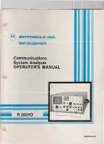
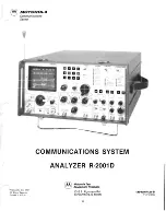
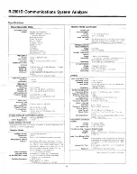
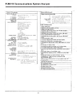
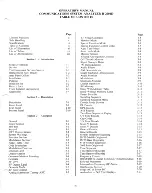
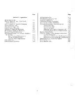
background image

Summary of Contents for R-2001D

Page 1: ...I a d ba Isal JNI Ol lO LOW n N II I S l I 01 l I3dO JaZAIBU walsAS suollBolunwwoo II II a iii tlDDIl f tI tI III _ 8 99V69018d89 ...

Page 2: ...st eqUipment in the U S contact the Test Equipment Service Cenrer Schaumburg 1313 E Algonquin Rd Schaumburg Illinois 601 or call the Te t Equipment Service Hotline 800 323 6967 during normal business hours In Illinois call 1 3J2 576 70 5 Outside the l S con a t your nearest 10torola representative MODULE EXCHANGE PROGRAM Modular onslruclion o he R_ I allow field replacement of individual assemblie...

Page 3: ...ElEI allEl OWER Ct J OISPI A I F JNCTION iCMotorola Inc 1985 All Rights Reserved Printed in U S A COMMUNICATIONS SYSTEM ANALYZER R 2001 D Motorola Test Equipment Products 1313 E Algonquin Rd Schaumburg lL 60196 iii 63P81069A66 B 7 15 85 PHI ...

Page 4: ... AI ...

Page 5: ...ble avoid touching any elec trically conductive parts of the circuit module with your hands 3 Normally circuit modules can be inserted or removed with power applied to the unit However check the INSTALLATION and MAINTENANCE sec tions of the manual as well as the module schematic diagram to insure there are no objections to this prac tice 4 When servlcmg a circuit module avoid carpeted areas dry en...

Page 6: ...onnected to CMOS vi device inputs after power is applied to the CMOS cir cuitry Similarly such low impedance equipment should be disconnected before power is turned off 11 Replacement modules shipped separately from the factory will be packaged in a conductive material Any modules being transported from One area to another should be wrapped in a simlar material aluminum foil may be used NEVER USE ...

Page 7: ...rophone or all Output Level 35 dBm minimum inlO 50 ohm load Simultaneously Deviation Range oto 20 kHz peak AMPLITUDE Frequency Response 5 Hz 10 20 kHz 3 dB MODULATION OSCILLOSCOPE Range 01080 Irom 1 to 500 MHz CRT Size 8 em x 10 cm Externalllnternal Frequency Response DC 105 MHz 3 dB point Frequency Range 5 Hz 1010kHz 3 dB External Vertical External Input Approx 150 mV lor 80 Input Ranges 10 mV 10...

Page 8: ...olts RMS into 600 ohm R 200BD With cellular option Input Impedance 10 K ohms minimum R 20080lHS High stability oscillator and cellular option SINADIDISTORTION METER R 2009D With IEEE 4BB Bus and cellular options Input Level 05 V 10 10 Volts RMS R 2009DIHS With high stability oscillator IEEE 48B Bus and cellular SINAD Accuracy 1 dB al 12 dB SINAD option Distortion Range 1 to 20 R 20100 With UK cell...

Page 9: ...iption Signaling Sequence 3 11 Signaling Sequence Menu 3 11 Description 2 1 Decode Mode Screens 3 11 Front Panel 2 2 PL Decode 3 12 Rear Panel 2 10 DPL Decode 3 13 Bottom Panel 2 10 A B Encode 3 13 Two Tone Sequential Paging 3 13 Section 3 Operation 5 6 Tone Encode 3 13 Cap Codes 3 14 General 3 1 5 6 Tone Decode 3 14 Power Section 3 1 Select V Encode 3 14 Self Test 3 1 Select V Decode 3 15 Keypad ...

Page 10: ...4 9 4 9 4 11 4 13 4 15 4 15 4 15 4 16 4 19 4 21 x Page AM Modulation Test 4 23 AM Modulation Linearity Test 4 24 Analyzer IF DISPLAY 4 25 Community Repeater Modulation 4 26 Wire Line Remote Base Modulation 4 28 Wire Line Remote Base Phone Line Levels 4 30 Phone Line Levels 4 30 Transmit Line Input 4 30 Receive Line Input 4 30 Measuring Levels Across A Balanced Lin 4 32 Generating Signals Across A ...

Page 11: ...etering Display 3 6 Power Measurements 4 17 3 15 Monitor Section 3 8 4 9 Audio Distortion Setup 4 18 3 16 Modulation Display 3 9 4 10 Audio Frequency Response Setup 4 20 3 17 Spectrum Analyzer Display 3 9 4 11 Audio Frequency Response 3 18 Duplex Generator Section 3 10 EIA Standard RS 152B 4 21 3 19 Duplex Generator Display 3 10 4 12 AM Modulation Test Setup 4 22 3 20 RF Memory Display 3 10 4 13 A...

Page 12: ...cial Function Control Codes Audio Filter Characteristics Valid PL Codes Valid DPL Codes Page 2 2 3 3 3 4 3 4 3 7 3 9 3 12 3 13 xii Table 3 7 Cap Codes 3 8 Select V Sequence Specification 3 9 iMTS Error Messages 3 10 Tone B Functions 3 11 Valid Input Frequency Versus Display Resolution 3 12 External Wattmeter Elements Page 3 14 3 14 3 16 3 17 3 18 3 19 ...

Page 13: ...nt Demodulation Deviation Disconnect Dispersion Distortion Division Delay Digital Private Line a Motorola regis tered trademark Duplex Double Sideband Suppressed Carrier Digital Voltmeter Encode Decode Electronic Engineering Association Electronics Industry Association External Frequency Modulation Frequency Forward xiii IC ID IDC IEEE IF 1M IMTS in I O Kohm kg KHz LED LPFL Lvi MAX MHz MIC or mic ...

Page 14: ...der Test SEC or sec Second V Volts SEL Select VAC Volts Alternating Current SENS Sensitivity VCE Voice SEQ or seq Sequence VDC Volts Direct Current Sig Signal Vert Vertical Signal Noise Distortion VRMS Volts root mean square SINAD Ratio of Noise Distortion VSWR Voltage Standing Wave Ratio SSB Single Sideband I W Watts STD Standard WB Wide Bandwidth SW Switch SWP Sweep I XY Select Any Valid Number ...

Page 15: ...rms out of warranty repairs on a time and materials basis at competitive rates Contact the Motorola Test Equipment Service Center toll free at 800 323 6967 or at 312 576 7025 in Illinois Frequently under the direction of the Center via telephone a technician Ii troubleshoots equipment to isolate a defective module I 6 The Center then ships an exchange module immediat y tc I I 1 6 L I fO 111 MOTORO...

Page 16: ...a Parts Office including requests for part num ber identification and test equipment calibration or repair MOTOROLA AREA PARTS OFFICES MOTOROLA C E PARTS 1313 E Algonquin Rd Schaumburg IL 60196 Phone 800 323 6967 312 576 3900 1 2 MOTOROLA AREA PARTS OFFICES EASTERN AREA PARTS 85 Harristown Rd Glenrock NJ 07452 Phone 201 444 9662 TWX 710 955 5602 EAST CENTRAL AREA PARTS 12995 Snow Rd Parma OH 44130...

Page 17: ...sition The factory sets the LINE switch as ordered Units ordered as R 2001D 220 or R 2002D1220 will be pre set for 220 VAC and will have a 3 0A fuse installed Install a 3A fuse for 110 VAC operation and a lOA fuse for DC operation ALL OTHER COUNTRIES MOTOROLA INC International Parts Dept Schaumburg IL 60196 U S A Phone 312 576 6482 TWX 910 693 0869 Telex 722443 Cable MOTOL PARTS Foam pieces protec...

Page 18: ...RTP 1002A DELUXE TELESCOPING ANTENNA PN RTA 4000A 600 OHM LINE MATCHING TRANSFORMER Use for 600 ohm balanced lines PN RTL 1003A PROTECTIVE CANVAS COVER A rugged padded fabric cover protects the Analyzer from excessive field wear PN RTL 4056B RF DETECTOR PROBE PN RTL 4075A 1 TRANSIT CASE PN RTL 4065A 1 4 MODEL OPTIONS Cellular Test Functions Model R 2008D provides capability in one test instrument ...

Page 19: ...TORS AND CONNECTORS 2 0 DESCRIPTION The R 2001D Communication System Analyzer shown in figure 2 1 is a portable test instrument designed to monitor and service radio communications equipment over the frequency range of I MHz to 1 GHz Table 2 1 lists the Analyzer s con trols indicators connectors and their functions The Analyzer generates signals measures modulation and frequency errors and perform...

Page 20: ...l frequency standard oven has stabilized Continuously illuminated with the TCXO fre quency standard Enters variables into microprocessor memory and onto CRT screen selects variables from the memory for display changes previous entries Moves the cursor down only to the next available line on the screen skips preset permanent entries from the last line it returns to the top line Moves the horizontal...

Page 21: ...on 4 Duplex Gen CRT displays duplex generate fre quency and modulation depth on the generator out put or monitor frequency and modulation depth on the received carrier FUNCTION switch position selects the reading In this mode the Analyzer simultaneously generates and receives signals for duplex radio servicing The Duplex Generator pro vides enhanced capability to service equipment such as repeater...

Page 22: ...er s performance 9 Ext Wattmeter Select the element and the screen displays the forward and reflected power passed through that element mounted in the RTL 4055 watt meter adapter 10 IF The screen displays the 700 KHz IF signal from the monitor receiver for AM and SSB receiver servic ing 11 Scope AC The screen displays the voltage wave form applied to the vertical input AC coupled 12 Scope DC The s...

Page 23: ...erate mode 6 SWP 0 01 1 MHz Equipment performs as in 5 above except sweep width limits are 0 01 MHz to 1 MHz Controls the Code Synthesizer modulation source 1 Cont Continuous modulation signal output gen erates repetitive cycles 2 Off No modulation generated Terminates code sequences 3 Burst Generates a single cycle spring loaded returns to Off a PL Tone A Tone B Output is present as long as switc...

Page 24: ...ates when Tone B is selected for output 5 Tone Sequence indicator illuminates when the output is a tone signaling sequence Select the sequence on the Tone Memory display 6 Tone Remote indicator illuminates when the output is the sequence for a remote station Set A for guard set B for command tone on Tone memory display Selects the function to be displayed by the equipment as in dicated by the DISP...

Page 25: ...one bias and PUSH TO TALK GENERATE connection to equipment Uses RTM 4000 microphone or handset External modulation signal input Output connector for all modulation signals all signals combined Controls speaker output level In monitor mode selects IF bandwidth Wide BW is 100 KHz mod acceptance Narrow BW is 5 KHz mod accep tance In Gen FM mode selects modulation range 0 100 KHz deviation in WB or 0 ...

Page 26: ...tical input CAUTION During Tone Sequence mode entering a scope trigger delay prevents normal operation of scope triggering Controls the posItIOn of the CRT display when in the oscilloscope mode Vert o Horiz Vert switch Vert Vernier control VertiSinad Dist DVM Counter In connector Center small control knob Controls the vertical position of the CRT display Outside large control Controls the horizont...

Page 27: ...put level in generate mode Also serves as RF input level step attenuator in monitor and spectrum analyzer modes Allows input from Motorola ST 1200 series inline watt meter elements for measurement and CRT display of for ward and reflected transmitted power Select either On or Off Duplex output from DUPLEX port is enabled with switch On Output connector for duplex generator output Connector for the...

Page 28: ...equency See bottom panel AC and DC line fuses OPERATION 1101220 VAC 12 VDC FUSE lOA PART NUMBER 65 20404 65 10266 FAN POWER CELL BUS Frequency Standard 10 MHz control Connector Bus connector Recessed switch Power connector for the cooling fan Placement of I O connector when cellular service option is installed R 2008D BOTTOM PANEL Select either the internal 10 MHz frequency standard or an external...

Page 29: ...el and provides approx imately 50 minutes continuous operation Figure 3 1 shows a three position toggle switch located to the right of the keypad on the front panel and used to control the Analyzer s power supply ON The On or full up posItIOn of the toggle switch energizes all circuitry except the battery charger SELF TEST When the power switch is first turned on the Analyzer performs an internal ...

Page 30: ...monitored in both analog and digital forms Bargraphs aid the autoranging digital readouts Each bargraph has a base line calibration markers and intensified segment show ing the measured value When the Analyzer is switched into another mode the CRT instantly displays all perti nent information Use the dual control located at the lower right hand corner of the CRT to adjust the inten sity and focus ...

Page 31: ...lation data is not monitored In sweep function select either 0 01 1 MHz or 1 10 MHz range Use the Dispr Sweep vernier to control the sweep width The minimum position is fully counterclockwise and the maximum position is fully clockwise The code synthesizer generates either a single tone a multitone sequence or a DPL sequence in response to front panel and CRT display inputs Press a MODULA TION arr...

Page 32: ...radio pre emphasis clipping and frequency roll off The microphone push to talk switch switches the system from monitor to generate mode Adjust the external in put sensitivity or impedance with the External Level control for analyses with external instruments The Off position turns off the composite external modulation signal path 0 61 uV 111 4DBM 12 4PCT DIST SINAD 18 1 DB 60 0 4 74 DEV KHZ 4 75 1...

Page 33: ... to 999 9999 MHz Use the RF Scan control to perform a linear sweep to scan the center frequency up or down Switch to AM or FM Monitor FUNCTION to aid in positive identification and analysis of an input signal Listen to the demodulated output via the built in audio amplifier and speaker RF SWEEP GENERATOR Use the SWEEP FUNCTION modes to continuously sweep the RF generator output display bandpass fi...

Page 34: ...am the deviation alarm from 0 1 KHz to 99 9 KHz with 100 Hz resolution Enter special function code 78000 to disable the alarm 15 ANT displays only when the antenna input on the front panel is enabled ATTEN 0 displays whenever the RF Step attenuator is at a setting other than the 0 dB position and the monitor mode is in use Line 4 displays the input signal level at the RF In Out connector from 70 d...

Page 35: ...63 Counter 10 Hz resolution 64 Counter 100 Hz resolution 20 Monitor Clears all 2X monitor 65 Counter 1 KHz resolution special functions default 70 System Control Sets factory control states state default state 21 Monitor Enables 300 Hz LPFL 71 System Control Sets the current state 22 Monitor Enables 3 KHz LPFL as the power on state 23 Monitor Enables 20 KHz LPFL 72 System Control Initiates a syste...

Page 36: ... lev of 25 dRm 10 dB at the antenna port When the Signal Level LED illuminates it indicates an open posi tion unsquelched When the LED is not illuminated it indicates a closed position from threshold to tight squelch OFF THE AIR MONITOR Use the Analyzer s antenna port for off the air monitor ing The Analyzer receiver s 1 5 uV sensitivity allows off the air monitoring to measure transmitter frequen...

Page 37: ...eaker monitors the recovered signal in the monitor mode and the modulating signal in the generate mode The speaker drive signal is also applied to the receive audio pin of the microphone headset connector Use special function control to disable the speaker while maintaining the headset audio signal with volume con trol The audio signal frequency response ranges from 300 Hz to 20 KHz in the wide ba...

Page 38: ...e A fre quency remains in the table until it is changed Once programmed the memory provides one button recall to set the operating frequency and code for the preset fre quency Figure 3 20 shows a typical RF Memory table page The display allows page numbers from 1 to 4 When the page number is changed the display changes to reflect the information stored on the new page Enter all numeric values exce...

Page 39: ...ystem to turn on at any other configuration proceed as follows 1 Press an arrow key to select the desired DISPLAY 2 Press an arrow key to select the desired FUNCTION 3 Press a MODULATION key to select the desired Code Synthesizer Mode 4 Simultaneously depress both keypad cursor keys to obtain the special function display Enter code number 3 11 71 to enter the new configuration into the nonvolatile...

Page 40: ... 173 8 FREQ 076 3 YB 88 5 6B 179 9 CODE 186 2 ZZ 91 5 7Z FIGURE 3 22 PRIVATE LINE DECODE DISPLAY ZA 94 8 7A 192 8 PL DECODE ZB 97 4 M1 203 5 Select Signaling Sequence DISPLAY Monitor FUNC lZ 100 0 82 206 5 TION and PL Mode Use special function control to select the signal source for the decoder The decoder ac 1A 103 5 M2 210 7 cepts signal inputs from either the internal monitor demodulator output...

Page 41: ... sequence all the Signaling Sequence DISPLAY and Generate FUNCTION The timing format for this mode consists of Tone A for the programmed time followed by the programmed delay followed by Tone B for the pro grammed time followed by the second programmed delay This sequence will repeat in continuous position but generate only a single sequence in burst position SIGNALING SEQUENCE MODE SEL 2 ENTER 0 ...

Page 42: ...2 4 5 3 1 1 X FREQ 0082 1305 0741 1446 Hz 1164 1023 0429 TIME 035 035 035 035 SEC 035 035 035 NO INPUT SIGNAL FIGURE 3 26 5 6 TONE DECODE DISPLAY 4 1400 1270 1358 1358 1358 5 6 TONE DECODE Figure 3 26 shows the decode display on page 2 If the reset is activated by entering a 1 for START all decode information is replaced by dashes and the decoder sequence resumes If the decode sequence detects the...

Page 43: ...L DECODE DISPLAY GENERAL DECODE Figure 3 30 shows a display for the general ten tone se quence decode table on page 6 Frequencies and time durations are derived from the input signal Frequency is displayed up to a maximum value of 9999 Hz I Hz resolution No display in a FREQ field with a time duration in the TIME field indicates that a space oc curred between the preceding tone burst and the follo...

Page 44: ...anual SCOPE TRIG DLY 0 000 SEC FIGURE 3 32 IMTS BASE ORIGINATED DISPLAY IMTS BASE ORIGINATED Figure 3 32 shows a page 7 display allowing the operator to enter a 1 to 7 digit ID for the mobile being tested Enter a number in the most significant location Dashes replace the desired number of digits Enter the desired number of digits The other digit locations remain as dashes The processor responds to...

Page 45: ...el so that they can be coupled onto phone lines or any other place they may be needed Activate the tone bursts by selecting TONE REMOTE mode in the MODULA TION section of the front panel Select the two ap propriate frequencies of the tone bursts by program ming Tone A and Tone B frequencies in the Two Tone paging sequence Typical guard tone frequency Tone A is 2175 Hz Function tones Tone B vary by...

Page 46: ...deflection Too little signal causes a NO INPUT SIGNAL indication on the screen too high causes wandering or erroneous readings The display shows the calculated input frequency the five digit fre quency readout with operator selected resolution the acronym for the multiplier Hz KHz MHz and posi tion of the decimal point as identified in table 1 The system automatically ranges to display the best re...

Page 47: ...ATTMETER ELEMENTS INTERMEDIATE FREQUENCY IF MODE The Analyzer s IF envelope displays on the CRT when the IF mode is selected Use the IF mode to qualitatively and quantitatively assess a transmitter s amplitude mod ulation envelope 1 25 2 5 0 25 30 5 DB MODE SEL 3 ELEMENT NO 5 3 10 6 100 9 1000 DIST SINAD REV WATTS FWD WATTS 04 285 7750 MHz INPUT LEVEL 2 94 mV MONITORFM 30 DBM DVM MODE I AC VOLTS 2...

Page 48: ...enuator in order to maintain the correct harmonic relationship to the rf carrier Analog Bargraph Full Scale Range 0 125w 0 15KHz 0 100KHz 0 100070 0 300V oto 100 Dist 60db to Odb SINAD Wattmeter Element dependent 0 2 5w to l000w Function Power Monitor above 1w Frequency Error FM Modulation AM Modulation DVM AC or DC DIST SINAD Ext Wattmeter The horizontal time base generator provides a linear hori...

Page 49: ...er the non volatile RAM test on power up or if the operator initiates a self test with a special function 72 a checkerboard pattern is displayed on the screen see Fig 3 43 This serves as a visual check of the display to verify proper alignment of the CRT FIGURE 3 43 CHECKERBOARD PATTERN XX XX XX XX XX XX XX SELF TEST XX XX XX XX XX XX XX XX XX XX XX XX XX XX XX XX XX XX XX XX XX XX XX XX XX XX XX ...

Page 50: ...n for this type of error is shown in Fig 3 45 If a checksum er ror is detected in an PROM device then an alphanumeric specifier identifies the socket it is in M1 identifies the PROM device in the leftmost socket on the microprocessor board M2 the 2nd from the left M3 the 3rd from the left and so on The operator can enter a 0 to allow testing to proceed If no entry is made in a minute the test will...

Page 51: ...tain a permanent written log of all measurements and information important to your operation CAUTION These are typical applications and are not all inclusive Not every test works with every transceiver Motorola takes no responsibility for their accuracy applicability or safety Always refer to your own transceiver s service manual for recommended test methods and specifications The Analyzer s DVM i...

Page 52: ...ONH o SWP 01 1 MHt g MODULATION a Co Oll BUIst Code Synlh Mode o OPL o PL DPLtnv o rone o ToneS o _ SeQ o Tone Remole HOflz Yo EJ tHo R lnJOut d DlII I DVM COunl In len o Horil nANT SPEAKER MOBILE RECEIVER FUNCTION GENERATE FM PL 100 0 DIGITAL DIST READING RF LEVEL 50000 MHZ FREQUENCY DPL DPL CODE RF OUTPUT LEVEL lOOOuV 47 0DBM 5 0 PCT DIST SINAD 26 0 DB ANALOG SINAD INDICATOR 60 o DIGITAL SINAD O...

Page 53: ...tly from the keypad 4 Adjust 1KHz Level control for 60070 of rated deviation as indicated on the CRT To prevent spurious noise modula tion set MODULATION switch to Off and Ext Level control to Off a With a lOOOuV RF input level adjust the volume control to rated audio power output EIA RS 204 C specifies that the receiver be set to produce rated audio power before measuring 12dB SINAD b Read distor...

Page 54: ...SWP OI IMHI o T AemOI I MONITOR H fi W Iffi low N o_ tJ POWER 00 fi SI mrO J De 011 i AC O R Clr RFSc n o HOIII eat Ho 11 o HOIII ilw 1 0 GJ 0 Q0 g H CO UIIUTrdl srsrr lUU ItIfOTOROLA I Yen S n ClIDI O P I h W m ICAUTIO DVM Counle l CAUTIO DOllor 0 I UT 0 1lWUI r r RF SECTION OSCILLOSCOPE AFl 1 I HI EIIV S rc o MO CA T o p po o O To l o A Ul 2 S 1 0 paWlA 2S 1 hI DUPLEX GEN 0 10 to Nom On C Potlll...

Page 55: ... up the receiver audio gain to feed audio noise to the Analyzer at least 1 4 rated audio power Read the audio noise voltage fed to the Analyzer Note the noise reading REF in dBm 3 Set FUNCTION switch to Generate With all modulation off adjust RF LEVEL until display reads 20 dB less than REF above 0 OX the REF Voltage 4 Read the RF LEVEL reading required to produce 20 dB quieting in uV left side an...

Page 56: ...0 o SSBrOS8SC o ToneB o SUlpe C o SWP 10 MHI o ToneSeq o S opeOC o SWP Ot I MH o foneRemole J MONITOR High a WIClr La Nlno_Y POWER 00 ft Standby oco i e e OY nRndr AFScan o Ho il l lIlHorll Veri o Hori 2 GJ G G 0800 Inten l 8 Ver1ISIn Di 1 DVM Counlerln e KH COMIIIUlfIClTIOJl srSTUIAlUlUUl CAUTION IlS e EIIWanmele CAUTION DO rOT 1 1 rOWER MOTOROLA Output dO I RF SECTION OSCILLOSCOPE RF L el K rr E...

Page 57: ...in step 5 until the receiver s squelch just opens On the display read the coded squelch sensitivity in uV or dBm AUDIO POWER OUTPUT TEST 1 2 3 4 5 6 7 Set DISPLAY to Gen Mon Mtr and FUNCTION switch to Generate FM Enter the RF frequency and PL code Adjust attenuator and Variable controls to 1000 uV 47 dBm Adjust the I KHz Level control to 60010 of the rated deviation on the DEV KHz scale Push the V...

Page 58: ...IO FREQUENCY RESPONSE 1 IJ til I J tlb 8 Cl I I OdB REFERENCE LIMITS FOR LOUDSPEAKER USAGE 300 HZ 1 KHZ 3 KHZ LIMITS FOR HEADPHONE OR LINE USAGE FIGURE 4 4 AUDIO FREQUENCY RESPONSE EIA STANDARD RS 204C 4 8 ...

Page 59: ...audio level Repeat this step for each frequency tested 9 EIA RS 204C specifies the frequency response for NBFM receivers over the range of 300 to 3000 Hz as follows a Audio response for receivers using loud speakers shall not vary more than 2 dB or 8 dB from a standard 6 dB per octave curve with reference taken as 1000 Hz b Audio response for receivers using either headphones or telephones lines s...

Page 60: ...rSeq o StOptoe o SWP 0 1 MHz o ToneRt mOle g MONITOR Hl9h ft Wlde Lo_ W H o Y POWER 0 ft Su ndby OCOII i B c O en ReAdy YJ 2J0GJ GJ00 0000 _lnlens ly o FocU Dlsptl weep 8 HOIU Vort Min e fllHOll1 Vert OHOIr CO UlllCAlI0IlS srSTUI AIl lYW CAUTION 125 1 1 e EIIW flmtlt CAUTION DO lOT l rUT PIlWU MOTOROLA Output B RF Scan m w a RF level KHI Ell mSrc I Set QJ O E QP DUPLEX GEN u N m ye 1 Pasillon CC I...

Page 61: ...ully clockwise to 10 MHz 4 Enter the proper receiver frequency 5 Set RF Step attenuator to OdB and RF Variable control to mid range 6 Use the OSCILLOSCOPE Vertical control to move the horizontaljweep line to the bottom of the graticule Set the Ext V Div control to 0 01 and its inner knob fully clockwise to C I position 7 Adjust the RF output level to produce a CRT display at the lowest eadable lev...

Page 62: ...0 MHl o Ton Stq O oc 0 1 1 o Sco DC o SWP Ol IMHl o Ton R tnOl Q g J J MH OSCILLOSCOPE MONITOR RF SECTION It II v mStcl 1 ItSec RFL Ye E C Squtkh Volum COClt Synlhl EIIL l Anltnn CAUTION Sltp V f bl OS O O 0 0 0 00101 Pull AML m 1 I UT nltn OWfIl Pu h orr IMu Min orr Rl ln Oul DUPLEX GEN Im otiOpl 8 0 1 JIIl Lt el Q o Min M Von Harl H19h W1dt 0 Low 1 0 orr RFlnlOul orr Oulpu Vert SIn dIO 1 CAUTION...

Page 63: ...the local oscillator signal is coupled to the Monitor input Change FUNCTION to Generate and enter the proper carrier frequency Introduce sufficient signal level into the RF input to fully quiet the receiver and adjust discriminator to zero volts DC for receivers requiring such an adjustment For receivers with quadrature or more critical detectors adjust detector tuning control or local oscillator ...

Page 64: ...DPl o OVM DIST o CW o PlfOPllnv o E IWaltmfl t O M o TonIA 0 o SSB OS8SC o Tone8 o 0pIAC o SWP 1 10 MH o Tone Seq o kopeOc o SWP Ol MHz o Ton RemOle g MONITOR MIC AUDIO IN POWER 0 ft 8 6n ll y J kOIl i U c O en e C1 y 00G 0 0000 HI OR co u c nD S nSUIlllAlun MOTOROLA InienSlty I PO Q O MH 11 10 11 OSCILLO E o 7 T l OPEmS y 0 00 I t o ol 100 I h 15 I 0 1 1 Volume 10 AulO e _ Nalmal V po _ OW S1 IO ...

Page 65: ...rror indicated on the display 6 Refer to the radio s service manual to determine if POWER and FREQUENCY are within spec limits and de termine if any adjustments are required 7 Proceed to check MODULATION as follows a Turn off all modulation sources at the Mod Out of the Analyzer in order to check the level of PL or DPL deviation from the transmitter b Key up transmitter with appropriate PL or DPL ...

Page 66: ...Monitor receiver is fully quieted as in step A 3 above C In Line Power Measurements 1 Referring to figure 4 8 connect the RTL 4055B in line wattmeter adapter with the appropriate T l200 series ele ment in the 50 ohm antenna line with the arrow pointing towards the antenna Plug the adapter s cable into the Analyzer s Ext Wattmeter jack Refer to table 3 12 in this Manual for further description of e...

Page 67: ...MOOlIOr 8u l 8ouP Ctn RFMrmory o S g ngSrq Code S nlh Mod o FrtqCO ln e O M o PLrOPL o DVM DIST o Cw o PLIOPl lnv o EJ IW tlmete o AM o ToniA 0 o SS81DSBSC o Tonl8 o S op AC o S NP 10MH o Tone Seq o SeOPtOe o SWP O loll ll o Tone Remotl MONITOR Ouipul AN 1 CAUTION UUT l rUT own EllWanmeler CAUTION 125 UX e Horir Eat Hon v OHo ir IN LINE RTL 40568 W ST1200 SERIES ELEMENT rl ANT CONN TRANSMITTER FIG...

Page 68: ...o To 0 o SS81CS8SC OTOM8 o ScopeAC o SWP 10 MHI o Ton Seq o Sc cDC Osw o _ o _A _o gJ I MONITOR H A7 w o fro Low Nanowy POWER Slfn lD D O i B AC O tn R d Hg oz btHori If v rt o Hori I2J0G 00 0000 V rt Sin dIDlll DVM Counl III J CO UIIOIIOIS snU llun CAUIIO m ln e E IW llme le MOTORO A Output CAUTIO 00101 l Ilf OW l dO A p V CA j 0 I AML mO OWEll Anlenn Puah DUPLEX GEN 0 RF 1 Oul Mo Mu 011 RF In Ov...

Page 69: ...ter as shown in figure 4 9 3 Turn off the MODULATION switch Disable PL or DPL 4 Key the transmitter and adjust the 1 KHz MOD Level control for 60070 of full rated transmitter deviation on the Gen Mon Mtr DISPLAY 5 Select DVM Dist DISPLAY and mode 3 DIST SINAD Read transmitter DISTORTION from the display Unkey the transmitter 4 19 ...

Page 70: ...DS6SC o TOM 6 o scop lle o s wp 1 10 MH o To eSeq o Scopt OC o SWP 01 MH o ToneRemote I MONITOR Squeltll Volume ICodeSrnlhlYI E tle el o ft StanObv DCOII POWER i e AC Ow Fl ady 11011 EIIHD Ven o Hori 12J0G GJG 0800 lnl n IlY o Focu DlSPrlSWIlP 8 CO UIIClllGIS SlSHM UAlYHR MOTOROI A Oulput CIUTION O Do_or l rl 1 OW II RFSC ln r 0 RFL h 1 KHll EIIVI mSeC IJSeC Q E i o Z i DUPLEX G 0 c PO I O c O M V...

Page 71: ...on Mtr key the transmitter and adjust Code Synth Level control to provide 300 0 of rated transmitter deviation 5 Change DISPLAY to DVM Dist Note both the transmitter MIC Audio input level in dBm and the test frequency for later use 6 Repeat the above procedure adjusting Code Synth Level to maintain 30 of rated deviation for each frequency to be tested 7 Plot the data points obtained above in db re...

Page 72: ... oo AC o sWP OaAH o fo SC q o ScoprDC oSWP 01 1 MHz o Tone Remote 1 MONITOR Squelch Volum COO Sl nIIlL 1 Ellll e 1 H f f W IN lO_ N OW J AF clIr POWER 0 ft Sh l ldby JDeDf i B c O nRC lIlfy 2 00 0000 M I V HOII VeftlSlnldlDISl DVM Counle In Ell HOrIJ e Vert o Horir CO UIlCAllOIS SfSTE HlEII 115 UUTION CAUTION 00101 rUT 0 11 MOTOROLA Oulpul dB Q O I I MH r v RF SECTION OSCILLOSCOPE Q U i 0 _ E 4 DU...

Page 73: ...LAY to DYM Dist and the AC voltmeter function 4 Adjust the I KHz Level control to provide the proper input signal level to the transmitter Refer to the transmitter s service manual to obtain the value for this level 5 Key the transmitter Read 0J0 AM on the display Change to IF DISPLAY to observe the RF envelope s distortion 6 To check the transmitter s distortion connect the Analyzer s Demod Out c...

Page 74: ...int at one end This corresponds to 100070 AM modulation If necessary adjust the horizontal vernier control to make the display just fill the screen 6 Observe the resulting trapezoid figure The top and bottom sides of the trapezoid should be straight Any curvature indicates non linearity in the transmitter final amplifier stages MODULATION o Pl OP o PlO I Olo 0 10 1 Olo s q OlO ol C d S I1 _ 0 Oew ...

Page 75: ...14 shows a typical IF DISPLAY its modulated FM carrier with incidental AM and a formula for calculating AM Use the IF mode to view the modulation envelope of the RF signal to detect and examine incidental AM in FM modes and to check AM depth of modulation Because the IF DISPLAY provides only a qualitative indication use the Monitor DISPLAY with AM Monitor FUNCTION to determine precise AM measureme...

Page 76: ... repeater level 9 Set DISPLAY to Duplex Gen FUNCTION switch to Generate FM and Duplex Gen switch to On Set the MONI TOR Image Duplex switch to High or Low as required Enter the proper offset frequency 10 Move the display cursor down to PL or DPL and enter a PL DPL code used in the repeater 11 Turn off the 1 KHz Level control Set MODULATION switch in the Cont position and adjust Code Synth Level co...

Page 77: ...WER Y 2 0 G00 0000 tI I I o foe O lptISw ep 8 I il l BNCT MODULATION aC OI 8l 11t Code SJ nlh MOeM o PUDPL O l DP o Ton A o ToneS OTontS o T eAtl 1Ote I I I I I I I I I 1 fl ANT RECEIVER LEVEL COMMUNITY REPEATER rl ANT I I I I I I I I _ J FIGURE 4 15 COMMUNITY REPEATER MODULATION SETUP 4 27 ...

Page 78: ... attenuator setting to un squelch the monitor Too high an attenuator setting or too tight a squelch setting inhibits the modulation deviation display 5 Enter the proper transmitter frequency Move the display cursor down to DVM and enter 1 for AC mode Adjust the 1 KHz Level control for 1 VAC indicated on the display to put 1 volt of 1 KHz test tone into the transmitter modula tion limiter 6 Set DIS...

Page 79: ... o E IWallmtler O M o Tone 0 o SSBIOSeSC o TontS o SeopeAC o WP 1 10MHJ o TontSeC o SeopeOe o SWP 111 IMH o ToneR mole g l MONITOR POWER i B 1I C Dun Re dy 00G GJ0 0800 elntt I 8 M V HOfll Vertl n d Oi OVM Counte In Ell HO l e Vert o Horil COlllllttJlltCAtlO S SfSlllllAlAllWI CAUTION 125WIilU e Ell Wattmeter OUlpul CAUTION O oo or IIPUT 0 11 1 d _ _ i l II _ I I III BNCT I ANT I I IDe I WIRE LINE ...

Page 80: ...e proper transmitter frequency Move the display cursor down to DVM and enter 1 for AC mode 4 Adjust the 1 KHz Level control for the DBM level expected from the remote control console The typical value of 16 dBm will be 4 dB of most actual levels 5 Remove the cable from the DVM Counter In connector coming from Mod Out Connect the cable coming from the line driver output to DVM Counter In 6 Adjust t...

Page 81: ...ToneA o Tane8 o Ton Stq o Tone Remote RCVR I I I I I I I I I I I I I FUNCTION IDC t DISPLAY POWER I I I J STATION RF CONNr ANT L _E I I I I I I 1 I I I I 1 1 1 LIM H f YJ 2 0ill0 G i 00 COlllMlIIlIC I lI011S SYSI lIlUAlfl ll LINE DRIVER CIRCUITRY OTOROLA 600n rl r _ J W J BNCT I I I I C l I I I I FIGURE 4 1 7 PHONE LINE LEVELS SETUP 4 31 ...

Page 82: ...to the DVM Counter In jack as shown in figure 4 18 Set the BALUN switch in the OPEN position 3 Set DISPLAY to DVM AC mode Measure the test tone level on the phone line by interpolating the AC VOLTS DBM scale on the display 4 Set DISPLAY to Scope AC Analyze waveform and measure AC volts peak to peak by interpolating the volts per division 5 With the BALUN switch in the OPEN position the BALUN repre...

Page 83: ...nttlMoclI o FleqCollntlr 0 o PllOPL o DVM DIST o CW o PLfOPlln o Elt Willlmell o A o TOfl 0 o SSltOSB C o OM I o ScolMAC o SWP 1 10MH o TonlS q o SCope OC oSWP 01 HI C 10 R ot 1Yl J MONITOR On StlndbY Dc 011 POWER i AC O nt leld 2 0 J 00 0800 U_lo 11011 SJST lIU i l 1I IfIfOTOROLA dB I I I I I I I I L BRDG BALUN 25C84202A01 T201 FROM T1380 1 I I I I I I I I I R T L LINE D RIYER MODULE FIGURE 4 18 ...

Page 84: ...ol commands 4 Set MODULATION switch to Cont Tone Remote High level guard tone function tone and then the continuous low level guard tone will go out Adjust Code Synth Level control for 30 dBm level of low level guard tone on the phone line as interpolated from the DBM scale This is equivalent to 0 dBm speech test tone level 5 Switch to Burst position each time that a tone remote control command se...

Page 85: ...0MH OToncS o SCOp4 DC o SWP Ol 1 MHz o TOIlI Rernoli MONITOR Oemod Oul BfD 0 POWER On SI l dbY DcOIf Horil fat Hor t Yen CHonz V n S n_dIOi DVM ColHtl r 2 0 G00 0800 CI IIIUIICAnUIS nsn lm f0 mwau e EatW ttmetltr MOTOROLA 1M CAUTION 00 lOT II ar de RFSun lnl s l 0 0 0 8 1 RF SECTION J OSCILLOSCOPE CAUTION 0 R L p bI E f 0 fo L 2 o S O D Ji Pull A 2 1 ell DUPLEX GeN 0 RF fOul 10 I AUIOpO IJOn NOlm ...

Page 86: ...ort 2 Set DISPLAY to Duplex Gen FUNCTION switch to Generate and attenuator to lOdb 3 Change the FUNCTION switch to Monitor Enter pass frequency on the display Set the offset to 0 MHz 4 Change DISPLAY to Spectrum Analyzer Set Dispr Sweep control fully clockwise to 10 MHz Turn the Duplex Generator on 5 Tune the cavity or both cavities in the duplexer leg to a peak indication on the display s center ...

Page 87: ... IWa lmeltf o AM o Tone A 0 o SS81DSeSC o Ton I o Scop AC o SWP1 OMI1 o Ton Seq o Scope DC o SWP 0 1 MHI o TonlR mOle g MONITOR H ft w fi LOw Nlrrow t f hi Morir POWER 0 StandbY OcOIl i 11 AC Oven Reildy 2J0G GJ00 0000 _ ens lv o Focus 8 COILUIUllltAllOIlS srsrUIAW trm 11UtiU CAUTION CAUTION DO IIT tl UT wn f yMOTOROLA O Oll Outpul A O CA IIVUl rown DUPLEX GEN o o RF SECTION Jr OSCILLOSCOPE _ V I ...

Page 88: ...pass band knobs of the cavities in the duplexer receive leg for a peak reading on the receiver limiter meter Reduce the signal generator output as necessary to keep the receiver limiter meter reading below satura tion This completes the pass band adjustment for the receiver leg 6 Set the FUNCTION switch to Monitor FM and the attenuator to 30 dB For low power transmitters it may be necessary to red...

Page 89: ...lmeter o OM o Ton A 0 o SSB OSBSC o ToneB o copeAC o WP I IOMHI o To Seq o Scope DC o WP 01 1 MHI o ToneAtrnol MONITOR 0 SI tMbY 0 011 POWER i B c o enRud 00 00 0800 v HoriJ v S d O SI OVMICou leorl EJllolot J e Vu o HoriJ RFln OUI conu unaIS snnM Ul llll CAUTION Il W In e CAUTION 00 lOT 11 1l1 own MOTORO A o Oll Oulp o CAUTION O DOIOJ I ur aW 1 DUPLEX GEN RF SCI _lnlenSlly 0 o oc O S 8 r AF SECTI...

Page 90: ...itch to Monitor and attenuator to 30 dB Verify that the display s center frequency reads the same as the transmit frequency in step A 7 above 3 Key the transmitter and adjust the reject notch adjustments on the duplexer receive leg cavities for minimum signal on the display Change the attenuator as necessary to keep the signal on the display 4 Loosen the cavity reject adjustment nut and slide it w...

Page 91: ...0 MHr o Tone Seq o Focus O sp 5weep o 5 opeOC o SWP OI lMH o Ton Aemol Q MH OSCillOSCOPE MONITOR Kff Ed VI _ mSec f Sec E i QY Squelch Code S lhl t E llevel 0 0 0 0 0 S _ 0 Min 0 Im g Dph BW I KHrLevtl W V HOII H w 0 Lo Nllrrow 0 Vert S n dID 1 DIJMICounl H In II Ion DtmodO 1 B O ModOul E I MOd In e Vert 0 o HOt CD IUlur DlS S ST UIUrlU MOTOROLA RF SECTION RF Le QjAUTION Step o DO lOT 0 IIPUT owu ...

Page 92: ... to allow adequate signal to get through the duplexer and quiet the receiver Reduce the signal generator output as necessary to keep the receiver limiter meter below saturation 4 Adjust the reject notch adjustments on the duplexer transmit leg cavities for minimum signal level on the receiver limiter meter Change the signal generator output as necessary to keep the received signal up out of the no...

Page 93: ...F eq Counte o O MIDIST o Ell W ltm l 0 o ScopcAC o ScopcDC POWER On SlanO t lY OtOlI i O AC OvenR oy V t1 Ol lorit 12J00 GJ00 0800 ltIlCtlS t g Vct1t5tnadtDitt OVMfCoufll rlfl H CD llIllUIJCA1IDJlS SUU ll UnU CAUTION lZ5W lUX 1IIIOTOROLA dO RF Scan o I RF SECTION r OSCillOSCOPE v MONITOR KHII Eu VI ms t I t IlS C n ED 0 D 0_ TO jo nOlcn CA 0 F Yr r Ap n j DUPLEX GEN 0 Rf nIOu 10 l AUIOpOlilion No ...

Page 94: ...RF In Out to prevent the transmitter from keying up on repeat 3 Set DISPLAY to Oen Mon Mtr FUNCTION to Generate FM and enter the receiver frequency 4 Set the attenuator to 60 dB and the Variable control to mid range 5 Adjust the I KHz Level control for 3 0 KHz DEVon the screen 6 Reconnect the cable from RF In Out to the RF tap off and enable the transmitter to key up For example it may be necessar...

Page 95: ...Pll KGen RF Memory o llInallng eq Code Synlh Mode o F eqCounlCf o FM o PLlOPL o OVM OfST Ocw o PL OPLII I o E IW llmele o AM o Tone A 0 o SSS O BSC o Tont S o StopeAC o SWP 1 10 MHz o Ton SeQ o StOptOe o SWP Ol 1MHI o ToneRemole MONITOR Squelch VOlume COdeSyn tI Lvi E lle eJ 0 0 0 0 0 Oil Ma Min f of 011 Mod Out e MOd In TX VNTEHNA OP YOU 4 otYLOAO 58 80313837 OR SLN 63218 RF TAP OFF CuPL XER RX F...

Page 96: ... Note the RF LEVEL input value in dB on the display Use this value as the reference level to determine insertion loss and isolation values 5 Reconnect the cables to the isolator Duplex Gen to isolator input and RF In Out to isolator output 6 Note the RF LEVEL input value in dB on the display Subtract this value from the value found in step 4 to obtain the insertion loss in dB 7 Reverse the connect...

Page 97: ... o PL DCl l o DVM OI T o cW o Pl OPlltI o E I W nmrtrr 0 o To 0 o sse oses o ToneS o Scop C o SWP IOMH o Ton s q o StOp OC o SWP OHMH o Tone R tJlOlt MONITOR H ft W IN La_ N trow Y 0 Sllndby Dc 011 POWER B c OorrnRudy YJ000 GJ00 0800 H v Helll AFh Oul VeniSin dlCial OVM Counlt In e uMo v 0 0111 CAUTION n U_IUTK lS S1 1U AUIYlUl ItsW M u e CAUTION DOlor l rUT DWflt Output ISOLATOR I I I I I L 1_1 R...

Page 98: ...8v v ...

Page 99: ...PMENT SERVICE REQUEST FORM This completed form must accompany equipment returned for service CUSTOMER S PURCHASE ORDER NO I DATE I MODEL NUMBER I SERIAL NUMBER I DESCRIPTION OF PROBLEM I REQUESTED SERVICE I SHIP TO ADDRESS I SHIP VIA I Providing the information below will reduce the turnaround time on your Test Equipment Service MOTOROLA CUSTOMER NUMBER BILL TAG SHIP TAG 4 49 INTERNAL MOTOROLA ACC...

Page 100: ......

Page 101: ......

Reviews: