July, 2002
6880360B49-A
3
Installation
Mobile 1/4-Wave Antennas
and drill a pilot hole down through the roof. If
the interior light of the car is centered in the
roof, remove this light and fixture and drill
the pilot hole up through the roof at about the
center of the interior light mountings. This
centers the antenna mount on the roof and
allows for easy access.
2.
Drill a 3/4-inch hole from the top of the roof
until the saw bottoms. Use a Motorola hole
cutting saw (01-80382A25) or equivalent.
When the saw bottoms on the roof, it cleans
off the paint in a neat circle and assures good
contact with the locking nut.
IMPORTANT
For proper seating of brushing assembly,
remove burrs and scrape any foreign
matter from underside of hole out to at
least 1/8-inch from edge.
3.
Determine the routing of the cable from the
antenna mounting base to the radio set; then
remove the molding and trim necessary to
facilitate pulling the cable through.
NOTE
To ensure ease of assembly, thread the
locking nut on and then off the bushing
ass em bly before insta llation . This
removes any burrs which may be present.
4.
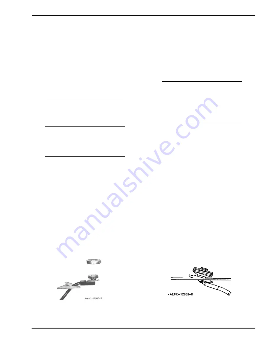
Refer to Figure 4. From the top, feed the
RG-58A/U lead-in cable between the headlin-
ing and the metal roof. Then route the cable
between the roof and the radio set.
5.
Refer to Figure 5. The bushing assembly is
now in a position to drop into the hole in the
roof. It should be tilted at a slight angle and
fed into the 3/4-inch hold. The threaded top
will not fall through the hole.
6.
Refer to Figure 7. Hold the antenna bushing
assembly in place with the index finger and
thread the locking nut onto it as shown.
7.
Pull up on the bushing assembly as illustrated
in Figure 8, and make sure it is centered and
seated (both shoulders inside the drilled hole),
and that the "O" ring is in the groove in the
locking nut. (As furnished, the "O" ring has
been placed in the locking nut groove and
imbedded in silicone grease.) Use a 15/
16-inch open-end wrench to tighten the lock-
ing nut until it bottoms firmly against the roof
top.
IMPORTANT
Refer to Figure 2. If the bushing assembly
should slip or rotate for any reason dur-
ing the tightening procedure, insert the
tips of a long nose plier or spanner
wrench into the two holes in the bushing
assembly and apply force to prevent
rotation until the locking nut is tight.
The locking nut
must
come into contact with the car
roof to insure the proper antenna radiation pattern.
This can only happen when the rubber "O" ring is fully
compressed.
8.
Take up the slack in the cable and replace the
headlining retainer molding.
9.
Replace headlining and dome light if
removed.
Installation Procedure - Double Wall Construction
Vehicles With Dome Lights or
Removable Headlining
1.
Remove the dome light from its mount or remove
the headlining from the installation area.
2.
Drill a small pilot hole centered in the roof of
the vehicle. The center of the cavity where the
dome light was removed is sufficiently close.
3.
Using a 1-1/4-inch diameter hole saw cut a
hole in the inside layer of the metal.
4.
Remove the metal and filler from this 1-1/
4-inch diameter hole.
Figure 4.
Coaxial Cable Insertion
Figure 5.
Bushing Assembly Insertion


