background image


RF Amplifier Quick Start Guide 

STARLINE

®


RF Amplifier 

Quick Start Guide 498160-001 

Motorola’s STARLINE RF amplifier series share many common features, functions and safety 
precautions. This Quick Start Guide is intended to cover basic installation and operation 
procedures common to all amplifiers. To obtain complete product documentation and compliance 
information for your specific amplifier, go to 

http://www.motorola.com/broadband

 and click 

HTML/Modem Version/Customer Support/Product Documentation/Manuals

Before you begin to install your amplifier, verify the model number and confirm that it 
accurately reflects the product configuration and options that you ordered. 

CAUTION! 


To avoid possible injury to personnel or damage to the equipment, remove 60/90 volt ac power from the system 
before you install the amplifier. 


Document Conventions 

Before you begin using the RF Amplifier Quick Start Guide, familiarize yourself with the 
stylistic conventions used in this manual: 

SMALL CAPS


Denotes silk screening on the equipment, typically representing front- and rear-panel 
controls and input/output (I/O) connections, and LEDs 

*

(asterisk)

(asterisk)

(asterisk)

(asterisk)


Indicates that several versions of the same model number exist and the information applies 
to all models; when the information applies to a specific model, the complete model number 
is given 

Italic type


Denotes a displayed variable, or is used for emphasis 

Installing the Housing 

STARLINE amplifiers are mounted horizontally below the strand or on a pedestal. To reduce 
the weight of the amplifier and prevent possible damage, it is recommended that you remove the 
electronics chassis before you install the housing. 

To install the amplifier on the strand, use the two strand clamp assemblies located on the long 
side of the housing and torque to 10 to 12 ft-lbs. 

To install the amplifier on a pedestal, use the bolts from the strand clamps and the two holes on 
the bottom of the housing. Torque the bolts to 10 to 12 ft-lbs. The centerline distance between 
the holes on the bottom of the housing is: 

Amplifier Model 

Distance Between Hole Centers (inches) 

BLE*/*


4.0 vertical centerline 

MB*/*, MBE*/*


7.7 horizontal centerline 

BT*/*


11.0 horizontal centerline 

Summary of Contents for RF Amplifier

Page 1: ... screening on the equipment typically representing front and rear panel controls and input output I O connections and LEDs asterisk asterisk asterisk asterisk Indicates that several versions of the same model number exist and the information applies to all models when the information applies to a specific model the complete model number is given Italic type Denotes a displayed variable or is used ...

Page 2: ...Vac for the HI position All units are shipped with the selector set in the LO position The LO position is used with 60 Vac systems where 38 Vac startup voltage is required For systems operating at 90 Vac the selector can be in the LO or HI position Note that changing the selector does not change the upper voltage limit but affects only the startup voltage The voltage selector should be switched on...

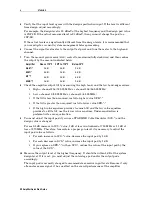
Page 3: ...r design values This is caused by factors such as walkout errors worst case data utilization during design and temperature variation from 70ºF 4 Secure the electronics chassis in the housing and torque to 18 to 22 in lbs to facilitate heat transfer 5 Perform a bench alignment Pre aligning the amplifier response on the bench for system signature simplifies field alignment If the unit is bench align...

Page 4: ... MHz or channel 3 61 25 MHz If the tilt is less than required install a higher value SFE If the tilt is greater than required install a lower value SFE If the high value equalizer provides too much tilt and the low value equalizer provides too little tilt use the lower value equalizer Under equalization is preferential to over equalization 9 You must adjust the input pad if you use a STARLINE Cabl...

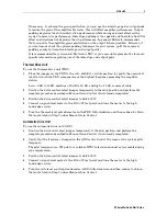
Page 5: ...plifier station Low 0 dB to 15 dB medium 15 dB to 30 dB and high 30 dB or more of cable 2 Position the drive control select jumper temporarily in the MAN position and perform the complete procedure described in Manual Gain Control if not already completed 3 Position the drive control select jumper to DRIVE UNIT 4 Connect a signal level meter to the FWD OUT test point and tune the meter to the high...

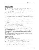
Page 6: ... output level The levels for the MBE assume a bridger gain 9 dB higher than the trunk Return Path Alignment The following subsections describe procedures required to obtain proper return path alignment Before You Begin For proper return path alignment obtain 1 RF alignment levels and insertion points for all amplifiers 2 RF reference output level of the headend optical receivers 3 A full complemen...

Page 7: ... reference level as compared to the node 11 Verify the sweep response of all insertion points if applicable 12 Verify that the pad and SRE values are similar to the map design values You can verify proper return alignment by injecting a carrier at the design level into any amplifier at random Proper alignment is achieved if you observe the reference level at the headend optical receiver output Ret...

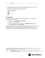
Page 8: ...lick Customer Support then click Web Support The TRC is open from 8 00 AM to 7 00 PM Eastern Time Monday through Friday and 10 00 AM to 5 00 PM Eastern Time Saturday When the TRC is closed emergency service only is available on a call back basis Web Support offers a searchable solutions database technical documentation and low priority issue creation tracking 24 hours per day 7 days per week MOTOR...

Reviews: