4-148
Motorola RF Switch System Reference Guide
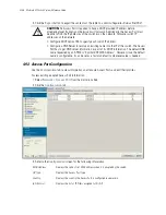
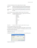
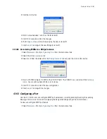
5. Select a template from the list below for the Access Port:
6. Enter a list of IP Filter Rules for the Access Port:
7. Select an IP Filter from the drop-down menu.
8. Select the
Enable LED for AAP
option to locate the Adaptive AP. The AP’s LED will flash indicating its
location in your setup.
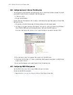
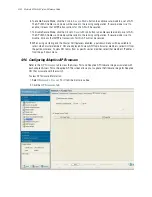
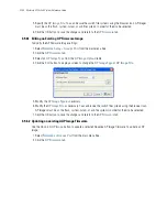
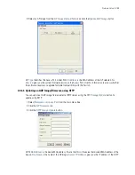
4.9.3.2 Configuring a Syslog Server on the AAP from the switch
To configure an external Syslog server on the AAP from the switch:
1. Select
Network
>
Access
Port
from the main menu tree.
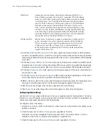
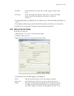
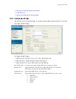
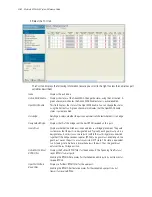
Native VLAN ID
Assign a unique VLAN ID (from 1 to 4094) to each VLAN modified. The VLAN ID
associates a frame with a specific VLAN and provides the information the access
point needs to process the frame across the network. Therefore, it may be
practical to assign a name to a VLAN representative or the area or type of network
traffic it represents.
AP Native VLAN for
LAN1
Select whether the native VLAN for the Access Port on LAN1 will be
Tagged
or
Untagged
.
Management VLAN
ID
Enter a
Management VLAN ID
for LAN1 and LAN2. The Management VLAN is
used to distinguish VLAN traffic flows for the LAN. The trunk port marks the
frames with special tags as they pass between the access port and its destination.
These tags help distinguish data traffic. Authentication servers (such as RADIUS
and Kerberos) must be on the same Management VLAN. Additionally, DHCP and
BOOTP servers must be on the same Management VLAN as well.
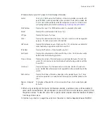
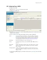
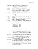
A/B/G/N WLAN and
Sensor
Enables 802.11a, 802.11b, 802.11g, 802.11bgn and 802.11an for the WLAN and
dedicates the AP as a sensor.
B/G/N WLAN and
Sensor
Enables 802.11b, 802.11g and 802.11bgn for the WLAN and dedicates the AP as
a sensor.
A/N WLAN and
Sensor
Enables 802.11a and 802.11an for the WLAN and dedicates the AP as a sensor.
A/B/G/N WLAN only,
no Sensor
Enables 802.11a, 802.11b, 802.11g, 802.11bgn and 802.11an for the WLAN and it
does not enable the AP as a sensor.
Sensor only
Spectrum Analysis
mode (no WLAN)
Enables the AP as a sensor and does not enable any 802.11a/b/g/n traffic.
B/G/N WLAN no
Sensor
Enables 802.11b, 802.11g and 802.11bgn traffic for the WLAN and it does not
enable the AP as a sensor.
A/N WLAN no
Sensor
Enables 802.11a and 802.11n traffic for the WLAN and it does not enable the AP
as a sensor.
Radios Off
Disables all radios on the selected Access Port.
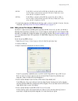
In Filters
Enter a comma-separated list of IP filters defined for the In direction.
Out Filters
Enter a comma-separated list of IP filters defined for the Out direction.
Summary of Contents for RFS Series
Page 1: ...M Motorola RFS Series Wireless LAN Switches WiNG System Reference Guide ...
Page 10: ...TOC 8 Motorola RF Switch System Reference Guide ...
Page 56: ...2 8 Motorola RF Switch System Reference ...
Page 334: ...5 52 Motorola RF Switch System Reference 2 Select the MU Status tab ...
Page 510: ...7 32 Motorola RF Switch System Reference Guide ...
Page 534: ...8 24 Motorola RF Switch System Reference Guide ...
Page 570: ...C 14 Motorola RF Switch System Reference Guide ...
Page 589: ......


