background image

Motorola Solutions RFS7000GR Series RF Switch Secure Installation Guide 

20

7. Define the user name used to access SFTP server. 

8. Specify the user account password to access SFTP server.

9. Specify the path to the firmware file. Enter the complete relative path to the file on the server.

10. Select 

Apply 

to start the firmware update. Select 

Abort 

to terminate the firmware update. Select 

Close

 to close the upgrade popup. The upgrade continues in the background.

11. Click the down arrow next to the device to view a set of operations that can be performed on the 

selected device, and click 

Reload

 button.

12. Login to the device using the default username ‘

admin

’ and default password 

0umP.s45fIOD6


’. 

Summary of Contents for RFS7000GR

Page 1: ...Motorola Solutions RFS7000GR Series RF Switch FIPS Installation Guide M ...

Page 2: ......

Page 3: ...Ethernet on the RFS7000 RF Switch 1 12 Rack Mount Instructions 1 16 RFS7000 Series RF Switch Console Port Setup 1 16 Supplying Power to the RFS7000 Series RF Switch 1 17 Verifying the Installation 1 18 5 Firmware Upgrade 1 19 6 Secure Installation Procedure 1 21 Upgrading the Wireless Controller from 4 X FIPS to 5 X FIPS 1 21 Upgrading the Wireless Controller from 4 X Non FIPS to 5 X FIPS 1 31 Com...

Page 4: ...ontroller RFS7000 s Password 1 45 8 Regulatory Information 1 46 Waste Electrical and Electronic Equipment WEEE 1 48 9 Motorola Solutions Enterprise Mobility Support Center 1 50 10 Motorola Solutions Inc End User License Agreement 1 51 ...

Page 5: ...e of patented Virtual AP architecture the RFS7000 Series RF Switch lets you create multiple WLANs without changing or adding to the existing wired network infrastructure This document is written for the network device installer 1 1 Package Contents Inspect the package contents and report any missing or damaged items to your sales representative The package should contain the following RFS7000 RF S...

Page 6: ...uipment damage due to a power surge or power failure Verify that the power connector and socket are accessible at all times during the operation of the equipment Do not work with power circuits in dimly lit spaces Do not install this equipment or work with its power circuits during thunderstorms or other weather conditions that could cause a power surge Verify there is adequate ventilation around ...

Page 7: ...Installation Guide 3 Verify that the RFS7000 Series RF Switch is powered through an Uninterruptible Power Supply UPS ...

Page 8: ...an help with the load balancing of these circuits Install surge protection Be sure to use a surge protection device between the electricity source and the RFS7000 Series RF Switch Install an Uninterruptible Power Supply UPS A UPS provides continuous power during a power outage Some UPS devices have integral surge protection UPS equipment requires periodic maintenance to ensure reliability A UPS of...

Page 9: ...tatus 1 LED System Status 2 LED Event Off Off Power off Green Blinking Green Blinking Power On Self Test POST running Green Solid Green Blinking POST succeeded Operating System Loading Green Solid Off POST succeeded Normal Operation Amber Blinking Off POST Failure Alternating Green Blinking Amber Blinking Alternating Green Blinking Amber Blinking Boot Up Error Device has an invalid checksum NOTE D...

Page 10: ... License to adopt Access Ports or No Country Code configured on the switch or License and Country Code configured but no APs adopted System Status 1 LED System Status 2 LED Event Off Off Power off Green Solid Off No Redundancy Feature Enabled Green Blinking Green Solid Redundant System failed over and adopting ports Green Blinking Alternating Green Blinking Amber Blinking Redundant System not fail...

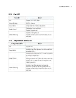
Page 11: ...eld in reset until the issue is resolved Temperature LED Event Off System Off Green Solid Ambient Inlet Temperature is within specified operating limit Amber Solid Ambient Inlet Temperature is near the maximum operating temperature During switch start up this LED will be lit Solid Amber This is normal behavior and does not indicate an error Amber Blinking Ambient Inlet Temperature is above the max...

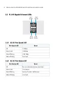
Page 12: ...RJ 45 Port Status LED Port Speed LED Event Off 10 Mbps Green Solid 100 Mbps Green Blinking 1000 Mbps Amber Blinking Port Fault Port Status LED Event Off No Link or Administratively shut down Green Solid Link present Green Blinking Activity Transmit and Receive Amber Blinking Link Fault sym_006 Port speed Port status Port speed Port status ...

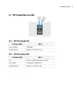
Page 13: ...3 2 SFP Port Status LED Port Speed LED Event Green Blinking 1000 Mbps Amber Blinking Module or Tx Rx Fault Loss Port Status LED Event Off No Link or Administratively shut down Green Solid Link present Operational Amber Blinking Module or Tx Rx Fault Loss s Port speed Port status ...

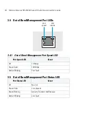
Page 14: ... Out of Band Management Port Speed LED 3 5 Out of Band Management Port Status LED Port Speed LED Event Off 10 Mbps Green Solid 100 Mbps Amber Blinking Port Fault Port Status LED Event Off No Link Green Solid Link present Green Blinking Activity Transmit and Receive Amber Blinking Link Fault sym_ Port speed Port status ...

Page 15: ...ed to them The sections that follow describe detailed connection and cabling information for each port NOTE The USB Compact Flash and 100 MB Ethernet ports are not available for the GR release of this product and are covered with tamper evident labels sym_005 Out of Band Management Gigabit SFP Port 1 Gigabit Ethernet Port 1 Console Compact Flash USB 1 USB 2 Gigabit Ethernet Port 2 Gigabit SFP Port...

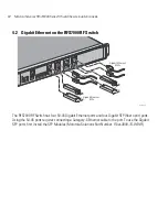
Page 16: ...00 RF Switch has four RJ 45 Gigabit Ethernet ports and four Gigabit SFP fiber optic ports Using the RJ 45 ports requires connecting a Category 6 Ethernet cable to the port To use the Gigabit SFP ports first install the SFP Modules Motorola Solutions Part Number Fiber 3000 1S WWR sym_013 Gigabit Ethernet RJ45s Gigabit Ethernet SFPs ...

Page 17: ...on Guide 13 4 2 1 Installing Gigabit Ethernet SFPs 1 Open the bail on the transceiver 2 Insert each of the SFP transceivers into the corresponding ports on the switch Open bail to insert or remove SFP transceiver ...

Page 18: ...FS7000GR Series RF Switch Secure Installation Guide 14 3 Once the SFP transceivers are properly seated in their ports close the bails to lock the transceivers in place sym_019 Open bail to insert or remove SFP transceiver ...

Page 19: ...Installation Guide 15 4 Insert the fiber optic cables into the installed transceivers ...

Page 20: ... steps are needed 2 Attach the brackets to the rack using screws appropriate for your rack s mounting holes 4 4 RFS7000 Series RF Switch Console Port Setup To add the RFS7000 Series RF Switch to the network and prepare it for initial configuration 1 Using the supplied console cable pictured below connect the RFS7000 Series RF Switch serial port to an RS 232 DB 9 serial port on a separate computer ...

Page 21: ... outlet with a voltage range of 100 to 240 VAC Terminal Type VT 100 Port COM port Terminal Settings 19200bps transfer rate 8 data bits no parity 1 stop bit no flow control no hardware compression WARNING An improper shutdown can render the RFS7000 Series RF Switch inoperable such that it could require service by Motorola Solutions Support Do not remove AC power without first following the shutdown...

Page 22: ...2 LEDs both blink green If the POST test fails the System 1 LED will blink amber If the POST test succeeds the System 1 LED will be lit solid green As the software is initialized the System 2 LED will blink green After the software has finished initializing the System 1 LED will be lit solid green and the bottom System 2 LED will be off Other LED codes indicate the presence or absence of different...

Page 23: ... selected device 3 Select the Firmware Upgrade button to upgrade the device s firmware 4 SFTP is the default protocol for updating the firmware 5 Use the spinner control or manually enter the value to define the port used by the protocol for importing the firmware upgrade file 6 Enter IP address or the host name of the server used to import the firmware file Use the drop down to select the type of...

Page 24: ... relative path to the file on the server 10 Select Apply to start the firmware update Select Abort to terminate the firmware update Select Close to close the upgrade popup The upgrade continues in the background 11 Click the down arrow next to the device to view a set of operations that can be performed on the selected device and click Reload button 12 Login to the device using the default usernam...

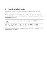
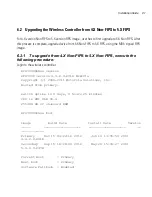
Page 25: ...set of default values for specific features These default values should be changed in order to maintain the security of the wireless users and access to the switch 6 1 Upgrading the Wireless Controller from 4 X FIPS to 5 X FIPS The following procedure explains the upgrade procedure to be followed when upgrading FIPS 4 X version to WiNG 5 X FIPS version NOTE All user inputs in this section are high...

Page 26: ...84 kB of on board RAM RFS7000 RFS7000 conf t Enter configuration commands one per line End with CNTL Z RFS7000 config RFS7000 config int ge 1 RFS7000 config if switchport access vlan 20 RFS7000 config if exit RFS7000 config RFS7000 config int vlan 20 Mar 06 06 50 23 2013 NSM 4 IFUP Interface vlan20 is up RFS7000 config if RFS7000 config if ip address 172 16 1 2 24 RFS7000 config if exit RFS7000 co...

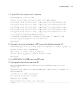
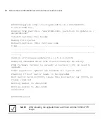
Page 27: ...5 packets received 0 packet loss round trip min avg max 0 4 0 9 2 8 ms RFS7000 3 Now export the running configuration to SFTP server using the below mentioned CLI RFS7000 copy running config sftp root 172 16 1 200 4 X_cfg txt root 172 16 1 200 s password Uploading to Downloads 4 X_cfg txt Downloads 4 X_cfg txt 100 0 0 0KB s 00 00 RFS7000 4 Copy RFS7000 5 4 10 0 037GB img on the SFTP server 5 Now u...

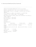
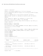
Page 28: ...s are handled via a patch file Checking if boot sector needs to be upgraded Boot Sector version 00003 image file bootsector ver 00003 no change required Writing Kernel to dev mtd5 Writing BootOS to dev mtd3 Successful RFS7000 RFS7000 sh boot Image Build Date Install Date Version Primary Nov 23 11 06 50 2011 unknown 4 1 1 0 003GR Secondary Mar 01 12 21 33 2013 Mar 06 07 03 07 2013 5 4 10 0 037GB Cu...

Page 29: ...sion 5 4 10 0 037GB Booting from NAND image2 0 ddr2 c 691 configure_ddr2 Clamping DIMM 0 speed at 533MHz 0 ddr2 c 829 configure_ddr2 Using SPD derived 533MHz DDR parameters Testing SAE 1 SHA256 hash successful SHA1 hash successful 3DES test successful AES test successful Testing SAE 2 SHA256 hash successful SHA1 hash successful 3DES test successful AES test successful Testing SAE 3 SHA256 hash suc...

Page 30: ...g flash startuplog This can take some time please be patient 4x to 5x configuration conversion in process 4x to 5x configuration conversion complete FIPS Power On Self Test started Wed Mar 06 07 04 49 2013 FIPS self test started this can take some time Wed Mar 06 07 04 49 2013 Creating integrity check file as a part of the update process Wed Mar 06 07 06 33 2013 FIPS integrity check of the WIOS im...

Page 31: ... successful Wed Mar 6 07 06 48 2013 6h HMAC SHA 512 hash successful Wed Mar 6 07 06 48 2013 The tests completed without errors Wed Mar 6 07 06 48 2013 KDF 135 TLS test successful Wed Mar 06 07 06 48 2013 openSSL power up self test successful Wed Mar 06 07 06 48 2013 FIPS power up tests for kernel space wireless crypto library Wed Mar 6 07 06 48 2013 Start Kernel space tests Wed Mar 6 07 06 48 2013...

Page 32: ... is enabled RFS7000 release 5 4 10 0 037GB This Device Is Running In FIPS Mode Attention This is a protected and private wireless system No un authorized access is allowed You must have proper rights to access and manage this system from authorized personnel Please press Enter to activate this console ...

Page 33: ... 1 2 4500 Mar 06 07 09 37 2013 AUTHPRIV 4 WARNING pluto 1417 adding interface pkt0 pkt0 127 0 1 1 500 Mar 06 07 09 37 2013 AUTHPRIV 4 WARNING pluto 1417 adding interface pkt0 pkt0 127 0 1 1 4500 Mar 06 07 09 37 2013 AUTHPRIV 4 WARNING pluto 1417 adding interface lo lo 127 0 0 1 500 Mar 06 07 09 37 2013 AUTHPRIV 4 WARNING pluto 1417 adding interface lo lo 127 0 0 1 4500 Mar 06 07 09 37 2013 AUTHPRI...

Page 34: ...r Windows and execute the below mentioned on command prompt PS C Program Files configuration converter cfgcv usage cfgcv version 4xconfiguration where version is 5 2 5 3 5 4 or 5 5 and 4xconfiguration is the name of the 4x configuration file PS C Program Files configuration converter PS C Program Files configuration converter PS C Program Files configuration converter cfgcv 5 4 4 X_cfg txt fivedot...

Page 35: ...Non FIPS execute the following procedure Login to the wireless controller RFS7000 show version RFS7000 version 4 4 2 0 001R MIB 01a Copyright c 2006 2011 Motorola Solutions Inc Booted from primary switch uptime is 0 days 0 hours 25 minutes CPU is RMI XLR V0 4 255484 kB of on board RAM RFS7000 show boot Image Build Date Install Date Version Primary Nov 15 04 22 16 2012 Jun 14 13 55 59 2013 4 4 2 0 ...

Page 36: ...me Version of firmware update file is 5 4 0 0 047R Removing unneeded files from flash crashinfo directory FPGA firmware version is already at version 3_29 no need to upgrade Power Supervisor updates are handled via a patch file Checking if boot sector needs to be upgraded Boot Sector version 00003 image file bootsector ver 00003 no change required Writing Kernel to dev mtd5 Writing BootOS to dev m...

Page 37: ...ime is 0 days 00 hours 27 minutes CPU is RMI XLR V0 4 Base ethernet MAC address is 5C 0E 8B 1A CE AB System serial number is 12040520400082 Model number is RFS 7010 1000 WR FPGA version is 3 41 rfs7000 1ACEAB upgrade sftp root symbol 172 16 1 200 RFS7000 SIGN_MD5 5 4 10 0 041GR img Jun 14 08 02 39 2013 rfs7000 1ACEAB DIAG 6 NEW_LED_STATE LED state message FIRMWARE_UPGRADE_STARTED from module led_m...

Page 38: ...be upgraded Boot Sector version 00003 image file bootsector ver 00003 no change required Writing Kernel to dev mtd4 Writing BootOS to dev mtd2 Jun 14 08 07 11 2013 FWU 6 FWUDONE Firmware update successful new version is 5 4 10 0 041GR Successful Jun 14 08 07 11 2013 rfs7000 1ACEAB DIAG 6 NEW_LED_STATE LED state message FIRMWARE_UPGRADE_ENDED from module led_msg rfs7000 1ACEAB J rfs7000 1ACEAB rfs7...

Page 39: ...Installation Guide 35 Next Boot Primary Software Fallback Enabled rfs7000 1ACEAB rfs7000 1ACEAB reload NOTE After reloading the upgraded device will boot with the 5 X FIPS image ...

Page 40: ...s allowed You must have proper rights to access and manage this system from authorized personnel admin 192 168 13 4 s password 2 Once Username and Password credentials are validated the switch will prompt to change the default password to a new value This prompt is only provided when logging to the switch for the first time Please change the default password of the admin user 3 Once Username and P...

Page 41: ... one per line End with CNTL Z G rfs7000 37FABE config 6 The console session will timeout after 180 seconds by default if no commands are entered To avoid this set the console inactivity timeout GUI or CLI to a higher value as shown below G rfs7000 37FABE config management policy default idle session timeout 1440 G rfs7000 37FABE config management policy default 7 Assign IP address to VLAN1 to make...

Page 42: ...with a default trust point using a default self signed certificate This certificate is associated with the hotspot and onboard RADIUS server This certificate should be replaced with a valid certificate from a Certificate Authority b Create a new trust point G rfs7000 37FABE crypto pki generate self signed t generate rsa key S subject name motoFIPS US CA SJ Motorola WLAN Successfully generated self...

Page 43: ...ficate G rfs7000 37FABE Import the Server certificate obtained from external CA using SFTP G rfs7000 37FABE crypto pki import certificate W sftp root symbol 172 16 1 1 ca Signed cert Signed certificate for Trustpoint W successfully imported G rfs7000 37FABE f Associate the newly created trustpoint with the hotspot feature using the example below G rfs7000 37FABE G rfs7000 37FABE self Enter configu...

Page 44: ...F38A RADCONF 6 RADIUSDSTART Radius Server Started Aug 06 02 06 10 2012 DAEMON 6 INFO radiusd 1903 Core dumps are enabled Aug 06 02 06 11 2012 DAEMON 6 INFO radiusd 1903 Loaded virtual server default G rfs7000 37FABE config device 00 15 70 37 FA BE Aug 06 02 06 18 2012 DAEMON 6 INFO radiusd 1903 Ready to process requests G rfs7000 37FABE config device 00 15 70 37 FA BE no use radius server policy G...

Page 45: ...00 37FABEAug 06 02 06 45 2012 ap7131 39F38A RADCONF 6 RADIUSDSTART Radius Server Started Aug 06 02 06 45 2012 DAEMON 6 INFO radiusd 1954 Core dumps are enabled Aug 06 02 06 46 2012 DAEMON 6 INFO radiusd 1954 Loaded virtual server default Aug 06 02 06 52 2012 DAEMON 6 INFO radiusd 1954 Ready to process requests rfs7000 37FABE i Write the changes to the memory G rfs7000 37FABE write memory OK G rfs7...

Page 46: ... 3 Scroll down to the bottom of the Advanced tab and ensure the Use TLS 1 0 option is selected Remember the RFS7000 does not support SSL 2 0 or SSL 3 0 4 Enter the IP address of the device within Internet Explorer Select the Continue to this Website not recommended option The default IP address is 192 168 0 1 At this point in the browser configuration a screen displays stating the Web site s certi...

Page 47: ...ion Click the OK button to continue A Security Error Domain Name Mismatch screen could display Click OK to continue At this point in the browser configuration a screen displays stating the Web site s certificate cannot be verified 5 Click Yes to continue The access point s login screen displays 6 Log in using admin as the default User ID and 0umP s45fIOD6 as the default password If the default log...

Page 48: ...D and 0umP s45fIOD6 as the default password If the default login is successful the Change Admin Password screen displays 4 Change the 8 64 character password to ensure the RFS7000 is using a secure password different from the default password Enter the current password and a new admin password in fields NOTE For advanced configuration options beyond the scope of this guide refer to the RFS7000 Pro...

Page 49: ...reless Controller s security to their default settings Only an installation professional should reset the Controller s password and promptly define a new restrictive password NOTE Though the Wireless Controller can have its basic settings defined using a number of different screens Motorola recommends using the Wireless Controller Initial Setup Wizard screen to define a minimum required configurat...

Page 50: ...operate the equipment Local language translations are available at the following website http supportcentral motorolasolutions com EN60825 1 1994 A1 2002 A2 2001 IEC60825 1 1993 A1 1997 A2 2001 The laser classification is marked on the device Class 1 Laser devices are not considered to be hazardous when used for their intended purpose The following statement is required to comply with US and inter...

Page 51: ... cause harmful interference to radio communications Operation of this equipment in a residential area is likely to cause harmful interference in which case the user will be required to correct the interference at his own expense Radio Frequency Interference Requirements Canada This Class A digital apparatus complies with Canadian ICES 003 Cet appareil numérique de la classe A est conforme à la nor...

Page 52: ...rhalb der EU Alle Produkte müssen am Ende ihrer Lebensdauer zum Recycling an Symbol zurückgesandt werden Informationen zur Rücksendung von Produkten finden Sie unter http www motorolasolutions com recycling weee Eesti EL klientidele kõik tooted tuleb nende eluea lõppedes tagastada taaskasutamise eesmärgil Symbol ile Lisainformatsiooni saamiseks toote tagastamise kohta külastage palun aadressi http...

Page 53: ...en dienen aan het einde van hun levensduur naar Symbol te worden teruggezonden voor recycling Raadpleeg http www motorolasolutions com recycling weee voor meer informatie over het terugzenden van producten Português Para clientes da UE todos os produtos no fim de vida devem ser devolvidos à Symbol para reciclagem Para obter informações sobre como devolver o produto visite http www motorolasolution...

Page 54: ...ephone or fax within the time limits set forth in support agreements If you purchased your Enterprise Mobility business product from a Motorola Solutions business partner contact that business partner for support Customer Support Web Site Motorola s Support Central Web site located at http supportcentral motorolasolutions com support provides information and online assistance including developer t...

Page 55: ...vice bureau purposes or otherwise use the Software for any commercial purpose on behalf of any third party Licensee shall maintain and not remove or obscure any proprietary notices on the Software and shall reproduce such notices exactly on all permitted copies of the Software All title ownership rights and intellectual property rights in and to the Software and any copies or portions thereof shal...

Page 56: ... with regard to the Software and the provision of or failure to provide Support Services ALSO THERE IS NO WARRANTY OR CONDITION OF TITLE QUIET ENJOYMENT QUIET POSSESSION CORRESPONDENCE TO DESCRIPTION OR NON INFRINGEMENT WITH REGARD TO THE SOFTWARE THE ENTIRE RISK AS TO THE QUALITY OF OR ARISING OUT OF USE OR PERFORMANCE OF THE SOFTWARE AND SUPPORT SERVICES IF ANY REMAINS WITH LICENSEE 7 EXCLUSION ...

Page 57: ... violation of any such restrictions laws or regulations By downloading or using the Software Licensee agrees to the foregoing and represents and warrants that Licensee is not located in under the control of or a national or resident of any restricted country 13 MISCELLANEOUS Licensee may not sublicense assign or transfer this Agreement or its rights or obligations hereunder without the prior writt...

Page 58: ...Motorola Solutions RFS7000GR Series RF Switch Secure Installation Guide 54 ...

Page 59: ...s com MN000262A01 Revision A October 2013 MOTOROLA MOTO MOTOROLA Solutions and the Stylized M logo are trademarks or registered trademarks of Motorola Trademark Holdings LLC and are used under license All other trademarks are a properties of their owners 2013 Motorola Solutions Inc All rights reserved ...

Reviews: