2 - 14 SE4750 Integration Guide
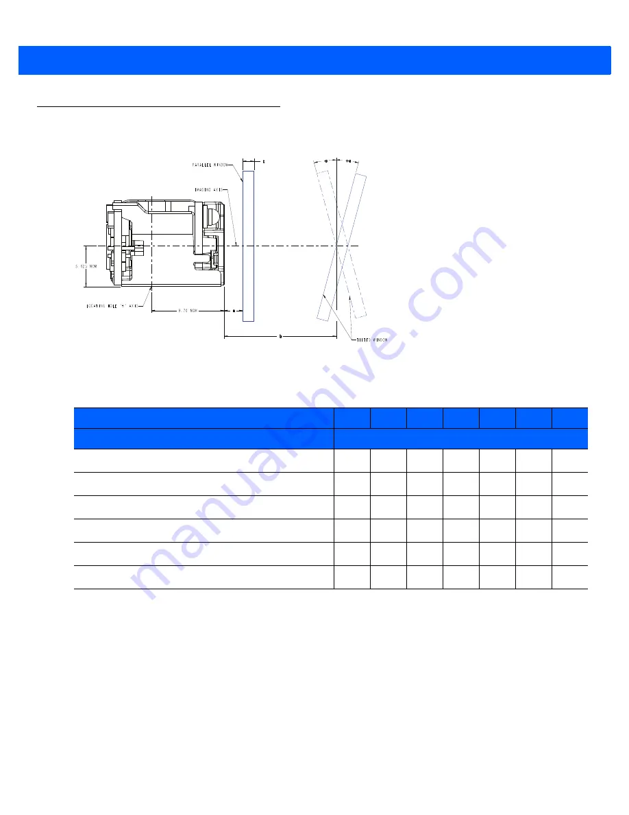
Recommended Exit Window Information
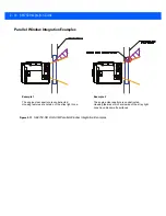
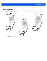
Figure 2-9
Window Distances
Exit Window Notes
•
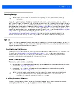
Do not place the exit window between the maximum distance for a parallel window (“a” in
) and the
minimum distance for a tilted window (5 mm in
) in respect to the front of the engine.
•
Integration tolerances are not included.
•
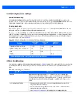
Ensure the window size is large enough to cover the engine clear aperture specified in
plus
mounting tolerances of the window relative to the engine.
•
Using a tilted window is not recommended for intelligent document capture (IDC) applications because dust
particles on the window surface scatter bright LED illumination and create image blemishes. The blemishes
are not harmful for bar code reading but degrade quality of IDC. For comparison, parallel windows are
located close enough to the engine that dust particles do not create image blemishes.
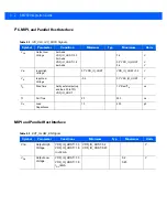
Table 2-4
Recommended Exit Window Information - Tilted Window
Distance from Engine Front Surface (b) in mm
5
5.8
10
12
15
20
25
Window Specification
Angle
Non-coated, minimum window positive tilt (+c)
+40
o
+40
o
+38
o
+37
o
+35
o
+35
o
+35
o
Non-coated, minimum window negative tilt (-c)
N/A
N/A
-52
o
-52
o
-27
o
-27
o
-27
o
AR coated, one side, minimum window positive tilt (+c)
+40
o
+40
o
+35
o
+35
o
+35
o
+33
o
+32
o
AR coated, one side, minimum window negative tilt (-c)
N/A
N/A
-27
o
-27
o
-27
o
-27
o
-27
o
AR coated, two sides, minimum window positive tilt (+c)
+37
o
+36
o
+33
o
+32
o
+31
o
+29
o
+28
o
AR coated, two sides, minimum window negative tilt (-c)
-18
o
-22
o
-25
o
-25
o
-25
o
-25
o
-25
o
Maximum Distance “a” for a Parallel
Window (all dimensions in mm)
Uncoated window:
a < = 1.69 - (t/n)
Single side coated window
(coated side toward engine):
a < = 1.94 - (t/n)
Double side coated window:
a < = 3.14 - (t/n)
where:
a
is the window distance from engine front
n
is the index of refraction of the window material
(typically 1.5 to 1.6)
t
is the window thickness
(typically 0.7 mm to 1.5 mm)
Anti-reflection coating specification:
Surface reflectance (avg) < 0.5% for
420 - 730 nm at 0 - 60
o
angle of incidence
Summary of Contents for SE4750
Page 1: ...SE4750 INTEGRATION GUIDE ...
Page 2: ......
Page 3: ...SE4750 INTEGRATION GUIDE 72E 171726 01 Revision A November 2013 ...
Page 6: ...iv SE4750 Integration Guide ...
Page 10: ...viii SE4750 Integration Guide ...
Page 14: ...xii SE4750 Integration Guide ...
Page 18: ...1 4 SE4750 Integration Guide ...
Page 29: ...Installation 2 11 Aiming Pattern Figure 2 6 SE4750 SR LSR AIM Optical Path Aiming Pattern ...
Page 36: ...2 18 SE4750 Integration Guide ...
Page 53: ...Electrical Interface 4 5 Figure 4 3 Parallel Host Flex p n 15 171522 xx ...
Page 66: ...5 12 SE4750 Integration Guide ...
Page 78: ...A 2 SE4750 Integration Guide ...
Page 82: ...Index 4 SE4750 Integration Guide ...
Page 84: ......
Page 85: ......


