1 - 2
SE4750 Integration Guide
SE4750
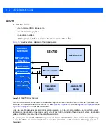
The SE4750 contains:
•
a monochrome CMOS image sensor
•
a laser based aiming system
•
an illumination system
•
a MIPI or parallel interface port and bi-directional control interface (I
2
C)
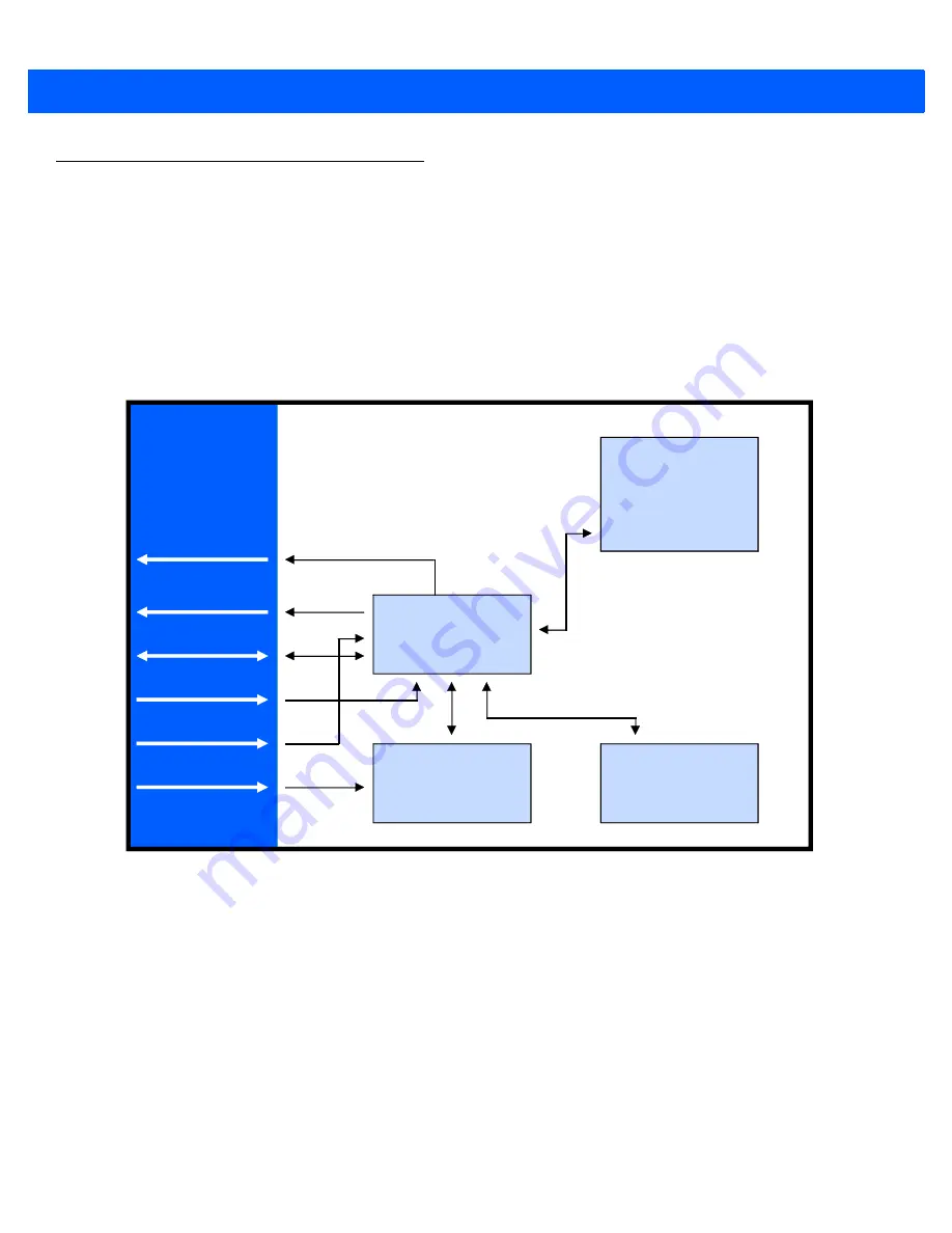
provides a block diagram of the imager system.
Figure 1-1
SE4750 Block Diagram
A 21-pin ZIF connector on the SE4750 connects the engine and the host device via a 55 mm flex (available from
Motorola). For information about this connector, see
. Also see
and
for host flex information.
A Visible Laser Diode and associated optics (aiming element) generate an aiming pattern, and dual, high output
LEDs provide illumination for the imager under virtually any lighting condition. The aiming subsystem, illumination
system, and frame rate are under dynamic software control.
The primary component of the SE4750 imager is a 1/3" format CMOS 1280 H x 960 V monochrome digital image
sensor. The CMOS sensor converts photons to a digital representation (8 bits per pixel) of the image present on
the sensor.
VCC
External I2C
DECODER
INTERFACE
Microcontroller
CMOS Sensor
Laser or LED
Aiming
SE4750
MIPI or Parallel
Interface
External Illum.
Illumination
System
VDD_IO_HOST
VCC (illum.)
Summary of Contents for SE4750
Page 1: ...SE4750 INTEGRATION GUIDE ...
Page 2: ......
Page 3: ...SE4750 INTEGRATION GUIDE 72E 171726 01 Revision A November 2013 ...
Page 6: ...iv SE4750 Integration Guide ...
Page 10: ...viii SE4750 Integration Guide ...
Page 14: ...xii SE4750 Integration Guide ...
Page 18: ...1 4 SE4750 Integration Guide ...
Page 29: ...Installation 2 11 Aiming Pattern Figure 2 6 SE4750 SR LSR AIM Optical Path Aiming Pattern ...
Page 36: ...2 18 SE4750 Integration Guide ...
Page 53: ...Electrical Interface 4 5 Figure 4 3 Parallel Host Flex p n 15 171522 xx ...
Page 66: ...5 12 SE4750 Integration Guide ...
Page 78: ...A 2 SE4750 Integration Guide ...
Page 82: ...Index 4 SE4750 Integration Guide ...
Page 84: ......
Page 85: ......


