Control Interface
5 - 3
Transactions
I
2
C transactions control the SE4750, where a transaction consists of a command followed by a response. I
2
C is a
master/slave protocol, meaning the host initiates both transmissions.
The SE4750 typically processes a command in less than 1 ms, but some commands take up to 100 ms. For this
reason, after sending a command, the host (I
2
C master) should request a response, and if the SE4750 does not
respond the host should retry the response request for up to 100 ms. If the SE4750 does not respond within this
time, a hard failure occurred.
The I
2
C format of these commands and responses is as follows.
I
2
C Command Format
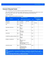
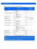
<I2C-Start Bit> <SLA-W> <Cmd-Opcode> <[SE4750-Cmd-Data]> <Checksum> <I2C-Stop-Bit>
where:
•
I2C-Start-Bit
and
I2C-Stop-Bit
are as defined by the I
2
C specification
•
SLA-W
is 0xB8 (Slave-Addr + Write-Op) or
•
Slave Address is 0x5C (or 0xB8 after shifting into 7 MSBs)
•
Write-Op is 0x00
•
Opcode
is 1 byte from the
SE4750 Command Op
column in
•
[SE4750-Cmd-Data]
is from the
SE4750 Command Data
column in
. This can be
NULL.
•
Checksum
is a 1 byte checksum of the
SE4750 Cmd Data
bytes. See
I
2
C Response Format
<I2C-Start Bit> <SLA-R> <Rsp-Opcode> <Status> <[SE4750-Rsp-Data]> <I2C-Stop-Bit>
Where:
•
I2C-Start-Bit
and
I2C-Stop-Bit
are as defined by the I
2
C specification
•
SLA-R
is 0xB9 (Slave-Addr + Read-Op) or
•
Slave Address is 0x5C (or 0xB8 after shifting into 7 msb's)
•
Read-Op is 0x01
•
Opcode
is 1 byte from the
SE4750 Response Op
column in
.
•
Status
indicates whether the SE4750 successfully processed the command. See
•
[SE4750-Rsp-Data]
is from the
SE4750 Response Data
column in
. This can be NULL.
Summary of Contents for SE4750
Page 1: ...SE4750 INTEGRATION GUIDE ...
Page 2: ......
Page 3: ...SE4750 INTEGRATION GUIDE 72E 171726 01 Revision A November 2013 ...
Page 6: ...iv SE4750 Integration Guide ...
Page 10: ...viii SE4750 Integration Guide ...
Page 14: ...xii SE4750 Integration Guide ...
Page 18: ...1 4 SE4750 Integration Guide ...
Page 29: ...Installation 2 11 Aiming Pattern Figure 2 6 SE4750 SR LSR AIM Optical Path Aiming Pattern ...
Page 36: ...2 18 SE4750 Integration Guide ...
Page 53: ...Electrical Interface 4 5 Figure 4 3 Parallel Host Flex p n 15 171522 xx ...
Page 66: ...5 12 SE4750 Integration Guide ...
Page 78: ...A 2 SE4750 Integration Guide ...
Page 82: ...Index 4 SE4750 Integration Guide ...
Page 84: ......
Page 85: ......

