3-8
Amplifier Setup
SLE*-* Installation and Operation Manual
PRELIMINARY - Motorola Internal Use Only
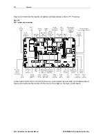
Figure 3-4 illustrates SLE*-* flatness and control ranges:
Figure 3-4
Typical flatness and control ranges
CH2 S21 /M log MAG
BLE87S/12/G
1 dB/ REF 30.49 dB
4: 30.757 dB
870.000 000 MHz
1: 30.434 dB
52 MHz
2: 30.306 dB
200 MHz
3: 30.394 dB
800 MHz
4
3
2
10:22:15
25 Jun 2001
1
PRm
C?
Del
14.7 dB P3-412 @870.0 MHz
START 52.000 000 MHz
STOP 900.000 000 MHz
Directional Coupler Test Points
Accurate
−
20 dB directional-coupler test points are available at the input and at the output of
the SLE*-*. Because these test points are 75-ohm source impedance, they do not require special
test probes.
After the output hybrid, a second directional coupler provides signal to the optional SLE-ADU
board. This signal is used only when the SLE-ADU board is installed. It is not necessary to
terminate this port when the SLE-ADU is not installed.
SLE-Bode Equalization
The optional SLE-Bode board, which is an electronically controlled equalizer, receives its control
input from either the SLE-ADU or SLE-TDU control boards. The response of the SLE-Bode
board compensates for cable attenuation changes due to temperature. If necessary, you can
control the SLE-Bode board manually using the potentiometer labeled Manual Level (
MAN
) in
Figure 2-8.
To install the SLE-Bode board, remove the chassis cover and remove the jumper at the (jumper
or optional SLE-Bode) location (Fig. 2-8). Replace with the SLE-Bode.


