39
are raised enough to see plating under them,
then the flex is not fully seated.
5. Reinstall the rubber controls top seal on the control top.
NOTE:
Two tabs are provided in the emergency button
area to help hold the seal in place.
Front Cover Assembly to
Chassis
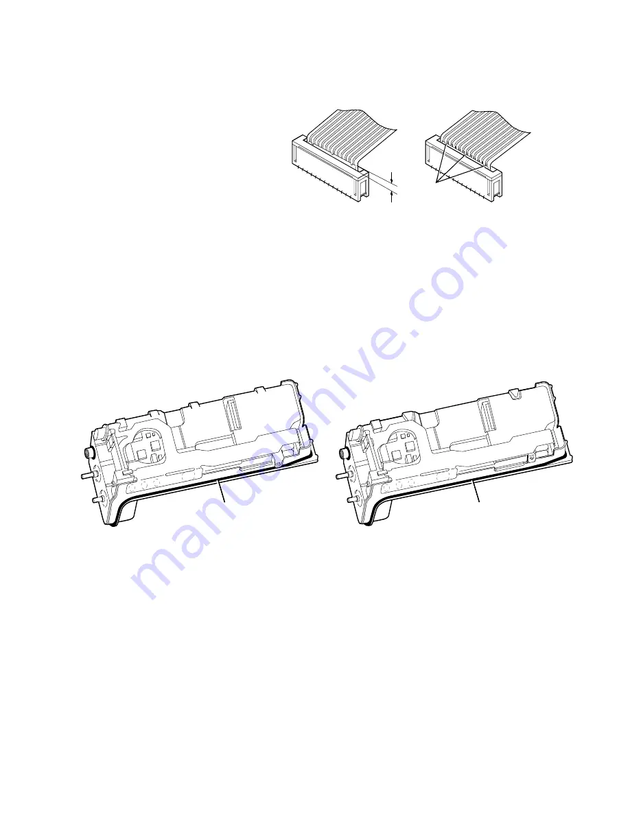
1. Install the contoured O-ring/antenna bushing seal around the
antenna and in the groove provided (see Figure 15).
2. Orient the front cover assembly with the chassis, and insert the
front cover/display flex connector into the locking connector of
the controller board (refer back to Figure 6). Secure the
connection. View the flex connection at a slight angle from the
top of the radio and ensure that the flex connector is fully seated
into the locking connector as illustrated in Figure 7.
3. Check to make sure that the O-ring is in place, and slide the
chassis (control top first) into the front cover assembly. Check to
ensure that the orange emergency button seal slides into position
freely.
NOTE:
When performing the next part of this step,
pay particular attention to the O-ring near the
bottom of the radio to ensure that it does not
raise up and get pinched between the front
MAEPF-22579-A
Flex Not Fully Seated
in Connector
Flex Fully Seated
in Connector
Misaligned
Plating
Reliefs
Figure 14 Seating the Flex
Figure 15 Installing the O-Ring/Antenna Bushing Seal
Contoured O-ring/
Antenna Bushing Seal
MAEPF-27018-O
Contoured O-ring/
Antenna Bushing Seal
Unit with
early Front Shield
Unit with
latest Front Shield
Summary of Contents for SYMBOL MT2000 Series
Page 1: ...HT 1000 JT 1000 MT 2000 MTS 2000 and MTX Series Handie Talkie Portable Radios Service Manual ...
Page 2: ......
Page 24: ...2 Notes ...
Page 78: ...56 Notes ...
Page 147: ...Appendix A 9 Appendix Figure 2 Secure Module Location Detail ...
Page 169: ......


