4-6
SE4400 Integration Guide
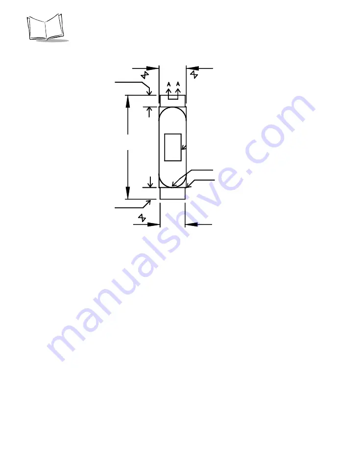
Figure 4-3. SE4400 to PL 4407-B000 Flex, p/n 50-16000-650
4.50 + 0.50
Polymide Stiffener
Far Side
10.50
See Note 6 & 10
40.00
2X R 5.25 +/- 0.50
12X R 0.20
4.35 +/- 0.01
9.50
Notes:
1. Dimensions are in mm.
2. Material: Base dielectric to be 1 mil polymide per IPC-4204/11 with 1/2 oz. copper clad.
Coverlayer(s) to be polymide per IPC-4203/1.
3. Finish: All exposed copper areas are to be white tin plated to a thickness of 25 microinches (average
thickness).
4. Workmanship standards shall be in accordance with IPC-6011 Class 2 and IPC-6013 type 1.
5. Supplied gerber data: Minimum conductor width 0.10 mm. Minimum spacing to be 0.08 mm. (except in
connector area).
6. Dimensions are to center of contact.
7. Scalloped ends are optional at covercoat termination in exposed finger areas.
8. Copper foil grain direction must be parallel with ZIF ends circuit conductors.
Summary of Contents for Symbol SE4400
Page 1: ...SE4400 Integration Guide ...
Page 2: ......
Page 3: ...SE4400 Integration Guide 72E 63399 04 Revision A January 2007 ...
Page 6: ...iv ...
Page 9: ...vii Contents Index Feedback ...
Page 10: ...viii SE4400 Integration Guide ...
Page 48: ...3 22 SE4400 Integration Guide ...
Page 78: ...5 20 SE4400 Integration Guide ...
Page 90: ...Index 4 SE4400 Integration Guide ...
Page 92: ......
Page 93: ......


