background image

Summary of Contents for System 6300 Series

Page 1: ...to install and hook up these peripheral units to your system Section 3 starts the user s guide portion of this manual The user s guide is intended as a reference for daily operation of your system Included in the user s guide is Section 3 which identifies all controls switches and indicators of your system and Section 4 which shows you how to maintain and care for your system Appendix A of this ma...

Page 2: ......

Page 3: ... Powering Up Section 3 Getting to Know Your System s Operating Mechanisms Section 4 Maintenance and Care Appendix A The Processing Unit and TM6000 Workstation Specifications Appendix B The Processing Unit and TM6000 Connectors Glossary 15 November 1984 iii iv ...

Page 4: ......

Page 5: ... 6300 Processing Unit Description 1 1 TM6000 Workstation Description 1 4 Illustrations 1 1 System 6300 and Printers 1 2 l2 System 6300 Disc Drives Connectors Status Indicators and the RESET Switch 1 3 1 3 TM6000 Workstation Components and Cables 1 5 15 November 1984 1 i ii ...

Page 6: ......

Page 7: ...00 is composed of the processing unit which has a fixed and a floppy disc drive to store information a TM6000 workstation which includes a video display unit a keyboard and a power module the various peripheral options like printers and the cabling necessary to connect the processing unit the TM6000 workstation and the peripherals together Figure 1 1 shows the processing unit hooked up to one TM60...

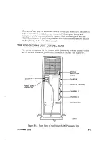
Page 8: ...py diskettes The System 6300 processing unit has the folloruing c onnectors on the rea of the processing unit the cluster connector to connect ternrinals the parallel printer connector to connect parallel printers channel 1to connect printers terrnilals or communication clevices and channel 0 to connect the first terminal to your processing unit with an R5 232 Cross cable The rear of the prrocessi...

Page 9: ...ators and the RESET switch STATUS INDICATOBS LEDr CLUSTER PARALLEL PRINTER CHANNEL T CHANNEL RESET SWITCH Figure 15 November 1984 7 2 The System 6300 Disc Drives Connectors Status Indicators and the RESET Switch FLOPPY REAB VIEW r o oN oFF swrTcH POIIEB CORD CONNECT R 1 3 ...

Page 10: ...haser Systems the TM6000 can produce split screens that can be scrolled independently of each oth er The TM6000 workstation as shown in Figure l Ii consists of the foltowing components o The video display unit with its base assembly o keyboard and coiled keyboard cable r The power module with one short power cord c ne long pow rr cord itnd one flat power cable o The RS 232 Cross cable and R5422 ca...

Page 11: ...R CORO TO SECONO POWER MOOULE POWER FLAT E POWER CABLE LONG POWER CORD TO WALL OUTLET Figure 1 3 TM6000 Workstation Components and Cables 422 CABLE RS 232 CROSS CABLE COILED CABLE KEYBOARD 15 November 1984 1 5 6 ...

Page 12: ......

Page 13: ...cessing Unit 2 2 Unpacking the TM6000 Workstation 2 6 Unpacking the Cables 2 11 Unpacking the Memory Expansion Board 2 I2 lnstalling and Powering Up the System 2 13 lnstalling a Memory Expansion Board 2 13 Installing and Powering Up the System 6300 2 26 15 November 1984 2 ilä ...

Page 14: ......

Page 15: ...to Open Cabinet Leave three feet of space to the left of the processing unit as you face the front of it You need this space so that the Field Engineer can open up the unit if the various internal parts need to be checked o Proper Ventilation The processing unit must be positioned in a spot where there is no obstruction at the front and rear of the unit s ventilation grilles Also make sure that th...

Page 16: ...CKING THE PROCESSING UNIT The processing unit comes in a large box cinched with two bands To urrpacl the processing unit perform the following procedure 1 Make sure the box is upright The oblong slot in the box shopl6l be 6t the bottom as shown in the following figure The Packed Processing Unit 15 N ovember 1 984 ...

Page 17: ...g the box See the following figure Fold back the box lids and following figure Also pull the box rernove the top piece of out the processing unit s A425AA foam as shown in the power cord from inside Cutting the Bands 15 November 1984 2 3 ...

Page 18: ...Proce ssing Unit Remove the box by lifting it upwards carefully leaving the procrzssing unit exposed and sitting in the bottom foamed box cal ed the carrier See the following figure 2 4 15 lovembe r 1g8 1 FOAM PIECE ...

Page 19: ...the processing unit and the other person grips the rear Each person should grip the top of the unit with one hand and underside of the unit with the other hand then lift carefully and place the unit on the floor Do not use the cable guide as a handle to lift the processing unit out of the carrier See the following figure 15 November 1984 2 5 ...

Page 20: ...his large box is a long power cord and three smaller boxes The largest of these three boxes is the video display box which contains the video display unit s screen and base The long nar row box is the keyboard bcx which contains the keyboard and a coiled cable l he smallest box is the pc wr r module box which contains the power module a short power cord and a long flat power cable These boxes are ...

Page 21: ...HORT POWER CORD TO SECOND POWER MODULE POWER FLAT POWER CABLE ULE LONG POWER CORD TO WALL OUTLET A3E868 The TM6000 Workstation Components unpack the TM6000 workstation Make sure the box is upright The figures outside the box should be right side up See the following figure To 1 KEYBOARD 15 November 1984 2 7 ...

Page 22: ...6000 box and gently lower the TM6000 box on its side and pull out the three boxes and the long power cord you fird inside See the following figure VIDEO DISPI AY uflrT Box POWER MOOULE BOX KEYBOARD BOX Unpacking the TM6000 Box LONG POWETI COFD 2 8 15 Novembe r 1984 ...

Page 23: ...ed in a piece of styrofoam Lift out the screen and base carefully to avoid damage See the following figure VIDEO DISPLAY UNIT 442644 Unpacking the Video Display Box Open the keyboard box and lift out the keyboard and the coiled cable found inside See the iollowing figure 15 November 1984 2 9 ...

Page 24: ...move lhe power module There is alsc a short power cord inside this box The por r er n Lodule box also contails a long flat thin power cable See the followirrg figure lvtODU L E SHORT POWER CORD FLAT POWER CI BLE A 4266A 2 70 Unpacking the Power Moclule Box 15 November 19114 ...

Page 25: ...get one RS 422 cable with each TM6000 workstation so that you can connect all the terminals together ln the cables box you will also find a terminator plug The terminator plug is inserted into the open connector in the last terminal when you have a series of TM6000 workstations connected to each other If you have only one terminal the terminator plug is inserted into the open cluster connector in ...

Page 26: ...irl of the box by pulling the flaps open See the following figure Opening the Memory Expansion Board Box The memory expansion board inside the box is urapped in static protection plastic Do not take the memory board out of the plastic wrap until you are ready to install the b ard into the processing unit If you are not goirrg to install the board immediately place it back in the box tc protect it ...

Page 27: ...ry expansion board or boards for your system skip the procedure about installing the memory expansion board and go on to the next procedure Installing a Memory Expansion Board To install a memory expansion board perform the following procedure L Place the processing unit so that as you face the front of the cabinet there are three leet of clearance on the left side of the cabinet for the cabinet s...

Page 28: ...DISCONNECTED Preparing to Open the Processing Unit Insert a small rod shaped tool such as a screwdriver into one of the trvc small openings located on the top of the processirLg unit as shouln in the following figure 2 t4 15 llovember 1984 ...

Page 29: ...ou have the screwdriver in the opening push down firmiy on the screwdriver while you force apart the outer casing at the seam of the cabinet until you unlock the irst lever lock See the following figure OUTER CASING Unlocking a Lever Lock 15 November 1984 2 15 ...

Page 30: ...e Aa27 A Opening the Cabinet CAUTION To prevent damage to the processing unit touch only those parts of the unit that you need to touch to insert the memory expansion board Pull the memory expansion board out of its protective plastic covering and place the board on a table on the board s plastic cover making sure the Zero Insertion Force ZIF pins are up and al the front of the board facirrg you S...

Page 31: ...o avoid damage ZIF PINS a 427 3 A The Memory Expansion Board Each memory expansion board has two memory the memory address range for the board Locate located on the front left part of the board labeled or E2 and E1 See the following figure addressing jumpers to set these jumpers they are either MA19 and MA20 f B B ilä r e B 15 November 1984 2 L7 ...

Page 32: ...g unit will come with the first expansion boarci factc ry instalied Yorl will be adding either a seconcl or a second and ir thirc expansiorL board Each board has a different setting NOTE The iumpers are set by placing them over twc of three pins available As you face the board a jumper is set to Or F if the jumper sit over its left pin 0 and its mirldle pin neutral A jumper is set to ON if it sits...

Page 33: ...ss j rupers are in the incorrect position on any of the expansion boards gently pull out the incorrectly positioned jumpers and push the jumpers over the correct pins indicated in the previous illustrations FIRST MEMORY EXPANSION BOARD FACTORY INSTALLED 15 November 1984 2 t9 Jo THIRD BOARD SETTING ...

Page 34: ... following oNl A4ta75A Setting the Memory Address Jumpers 10 With the memory board positioned so that front of the bcard pull the ZIF latch out as NOTE The Zero Insertion Force ZIF pins are any of these pins 11 Remove the six thumbnuts unscrewing thet thumbnuts figure t ioo z rffi iz VAC OV c vac to o9 iao e u o ac t ag c5 j 1t2 1oo c 1o ov e OV C c v c on a c 1 12 0 z e a t ff 15 l Iovember 198q1...

Page 35: ...uts 12 Place the memory expansion board s stud bolt holes over the processing unit s six threaded stud bolts and while holding the board with one hand insert the stud bolts into the stud bolt holes You may have to move the stud bolts a little to get them to fit into the board s stud bolt holes See the following figure Aa272A 15 November 1984 2 2L ...

Page 36: ... s ZIF connector pins Slide the memory exfransion board down until its ZIF conne tor almost touches the lower b oard s ZIF pins CAUTION Make sure to slide the memory expansion board Jown evenly over the stud bolts keeping it parallel to the lower board This ensures that the memory expansion board s ZIF connector lines up with the lc wer board s ZIF pins for an easy insertion that won t bend any pi...

Page 37: ...onnected securely to the lower board CAUTION ZIF stands for Zero lnsertion Force which means that the ZIF pins insert into the ZIF connector without force Therefore use care when mating the ZIF pins with the ZIF connector as force can cause damage Also the ZIF connector pins must be clean and straight to ensure proper insertion 15 After you have inserted the added memory expansion board into the l...

Page 38: ... expansion bcard tr add to your processing unrit repeat the steps 6 through 15 for the next m rlory boa rd installation 17 After you have inserted the memory boards screvJ on the six tl rumbnut s snugly to secure the boards A 4280A 2 24 Screwing on the Thumbnuts 15 l ovember 1984 ...

Page 39: ...l the latches and that there are no tools inside the unit bringing up the side panel and snapping it and thumbnuts are on secureiy close the processing unit by closed A428tA Closing the Processing Unit Side Panel 15 November 1984 2 25 ...

Page 40: ... insert into the connector See the foilo ring figure CAUTION Make sure thart you insert the coiled cable and not the flat pow u r cable into the keyboard connector These cables have similar ends and botl r can fit into the keyboard con ector A3a95B Inserting the Coiled Cable into the Video Display Unit lnsert the other end of the coiled cable into one f the two corrnectors located on the back side...

Page 41: ...ound so that you face the back of the unit 4 lnsert the RS 232 Cross cable into the serial connector located on the rear of the base assembly of the video display unit See the following figure NOTE The RS 232 Cross cable is used only to connect the first terminal to the processing unit NOTE Make sure to screw in the connector retaining screws after you insert the RS 232 Cross cable to secure the c...

Page 42: ...ing figure NOTE Screw in the connector retaining screws after you insert the RS 23 z Cross cable to secure the connection CAUTION To avoid tripping over cables or cords thread all your cables arnd power cords coming from the processing u nit through the cable guide locatecl on the lower rear of the processincy unit To prevent damage to the processing unit avoid using the cable guide as a handle to...

Page 43: ...nector Insert either end of the RS 422 cable into either of the cluster communication connectors located on the rear of the video display unit s base assembly See the following figure NOTE Screw in the connector retaining screws after you insert the R5422 cable to secure the connection A 389 6A 4 15 November 1984 2 29 CROSS CABLE ...

Page 44: ... the Cluster Co mmunications Connector 7 lnsert the othrzr end of theRS422 cable into the luster connector located on the rear ol the processlng unit as shown in the following figure NOTE Screw in the connector retaining screws after you insert the RS 422 cable to secure the connection Z 2 30 15 l ovember 198 1 ...

Page 45: ...cal power to your terminal start by inserting the flat power cable into the power connector located on the rear of the video display unit s base To do this press the clear plastic on either side of the cable end and while holding the clear plastic pressed insert into the connector See the following figure a 2 15 November 1984 2 31 ...

Page 46: ... CONNECTOR Inserting the Flat Power Cable into the Terminal While pressing the clear plastic on either side of thel cable end ir sert the other end of the flat power cable into the povuer module See thr following figure 2 32 15 I lovember 1984 ...

Page 47: ...to the Power Module 10 Pull back the black sticker on the power module to see if the voltage selection switch is set to 115 VAC or 220 VAC The switch setting should match the voltage output of your electrical outlet If incorrectly set change to the correct setting See the following figure 15 November 1984 2 33 ...

Page 48: ... Checking the Voltage Selection Switch the power module r long power cord into the rnale module See the followir g figure ASSEMBLY FLAT POWER CABLE 2 94 FEMALE R MODULE VOILTAGE SELECTION S WITCH Art4xSa LONG POWER coRu A4i 86A Inserting the Long Power Cord into the Power Module 15 Novembr r 19134 FLAT POWER CABLI ...

Page 49: ...to the Electrical Outlet NOTE If you are connecting more than one terminal to your system go through the following steps otherwise place a terminator plug into the open cluster communications connector see previous figure and go on to step 23 13 As you face the rear of the terminal insert either end of an RS 422 cable into the open cluster connector of the first terminal in your cluster of termina...

Page 50: ...erting the R5422 Cable into the Open Cluster Connector 74 Insert the other end of the RS 422 cable into one of the cluster communications connectors of your second terminal as shown in the following figure OIPEN C LUSTE R CICMMUNICATION CISNNECTOIR 2 36 15i Novembr r 19134 44288r ...

Page 51: ...4 until you have connected as many terminals onto your system as you need up to the limit of eight terminals 15 After you have connected as many terminals as you need make sure to insert a terminator plug into the open cluster communications connector of the last terminal in your cluster otherwise your terminals will not operate correctly See the following figure 15 November 1984 2 37 ...

Page 52: ...n connect each terrrinal in your cluster of terminals directly to an electrical outlet by following the previous steps 8 through 72 Tl te connected terminals should look as shown in the follovi ing figure NOTE Since you have performed the previous s teps 13 through 12 once th z first terminal in your cluster of termina s is already connected to an electrical outlet You have to connect the remainin...

Page 53: ...le and checking each power module s voltage switch setting as per steps 8 through 10 above See the following figure NOTE Since you have performed the previous steps 1l and 12 the power module of your first terminal in your cluster of terminals is connected to an electrical outlet with a long power cord Disconnect this long power cord from both the electrical outlet and the power module 4429 I A 15...

Page 54: ... Module 18 Next insert the female end of the short power cor d provided with each power module the cord is about 12 inches long into the male connectr r of the first terminal s power module See the fc llowing figure 2 40 15 Novemberr 1984 ...

Page 55: ...rting the Short Power Cord into the First Terminal s Power Module 19 Insert the male end of the short power cord into the female connector of the second terminal s power module as shown in the following figure 15 November 1984 2 41 ...

Page 56: ... Terminal s Power Module NOTE You can only connect two power modules to each other in the fiasl ion described in steps 18 through 19 above then yor mus t connect the second power module to an electrical outlet as will be describerd in steps 20 and 21 that follow 2 42 15 November 198i4 ...

Page 57: ... long power cord s female end into the second power module s male connector as shown in the following figure MALE CONNECTOR Inserting the Long Power Cord into the Second Power Module 15 November 1984 2 43 FEMALE END ...

Page 58: ...sert the long power cord s male end into a grounded three hc le electrical outlet See the lollowing figure Inserting the Long Power Cord into ern Electrical Outlet o t r L 1 MALE END 2 44 15 Itlovember 1984 ...

Page 59: ...e until eiectrical power Your setup should in your cluster of terminals as explarned all the power modules have a source of look as shown in the following figure Connecting One Power Module to Another then to an Electrical Outlet E L a 4297 A 15 November 1984 2 45 ...

Page 60: ... do this you plug in the female end of the processing unit s power cord into the processingl unit s male power cord connerctor See the follouring figure FEMALE END Inserting the Processing Unit s Power Cord into the Processing Unit MALE POWER CORO CONNECToR 2 46 15 ltlovember 1984 ...

Page 61: ...er for help Inserting the Processing Unit s Power Cord into an Elechical Outlet 25 Turn on the processing unit s I O power switch located directly above the power cord connector by pressing the switch to the 1 position See the following figure NOTE The indicator labeled number 2 located on the rear of the processing unit lights when the processing unit s I 0 power switch is turned on If the indica...

Page 62: ...utlet Make sure thal the electrical outlet is live by r witching on any suritch thal may give power to your electrical outlet If neither of th a two steps above light the indicator call your Fierd Engin zer for help Turning on the Processing Unit s Power Switch r 43OOA uo PowER swtTcH 2 48 15 November 1 984 ...

Page 63: ...following steps in order until you solve the problem Check to see that the cable connections connecting the terminal to the power module and the connections connecting the power module to the electrical outlet are secure Make sure that your electrical outlet is live by turning on any power switch that powers the electrical outlet Turn off the TM6000 terminal for a few seconds then power it up agai...

Page 64: ...or telling you something is happening or will happen v 1 0 Prompt B C E Frl rR SrT 27 Now that you haver powered up your system for the first time turn 6ff the terminal by pressing the terminai s power switch off See the foilow ing f igure rt 4 Turning Off the Terminal s P wer Switch 2 50 A3899 15 l lovember1984 TERMINAL S ...

Page 65: ...See the following figure Turning Off the Processing Unit s Power Switch Your system is now ready for software installation Do not proceed in this manual until you have installed your software into your system Consult lhe System 6300 Software Installation Guide for software installation instructions 15 November 1984 2 5L152 ...

Page 66: ......

Page 67: ...s and Indicators 3 1 The Processing Unit 3 1 The TM6000 Workstation 3 2 Loading and Unloading a Floppy Diskette 3 3 Illushations 3 1 Processing Unit s Switches and Indicators 3 2 3 2 The TM6000 Workstation Components Switches and Controls 3 3 3 3 Loading the Floppy Diskette 3 4 15 November 1984 ü r u ...

Page 68: ......

Page 69: ...ere the power cord connector is located See Figure 3 1 The processing unit has the following switches and indicators o The I O Switch the ON OFF switch Use this switch to turn the processing unit s power on and off o The Sfatus Indicators also known as LEDs These five indicators indicate the status of the processing unit as it goes through the boot procedure The boot procedure is that part of powe...

Page 70: ...nd switches have the follcwing functions o The Power Switch This switch turns on the power to the terr rinal lt is located on the left side of the video base assembly o The Brightness Control Use this control wheel to control the brightness o your screen displays This control wheel is locaterl underneath the left siide of the video Cisplay unit close to the power switch o The Power Module s Voltag...

Page 71: ...at the switch is set at by the factory LOADING AND UNLOADING A FLOPPY DISKETTE The floppy disc slot located on the upper front of the processing unit accepts the floppy diskettes which contain the software for your system To load the diskettes perform the following procedure 1 Power up the system 2 Push open a small latch that fits over the disc slot To open the latch press with your thumb on the ...

Page 72: ... lnsert the diskette only after powering up tne system and remove the diskette before powering down the system c therwise the data on your diskette could be destroyed Do not touch the diskette surface exposed by sl ts in the carrier envelope of the floppy diskette EXPOSED Drsc SUR FACE INDICATOR BLOCKED i LlGH rr OUT BY FLOPPV Figure 3 3 Loading the Floppy Diskette You are now familiar with the Sy...

Page 73: ...ining a Proper Environment For the System 6300 processing Unit 4 1 TM6000 Maintenance and Care 4 1 Maintaining a proper environment 4 1 Video Tilt and Swivel 4 1 Cleaning the Terminal 4 2 Care of Floppy Diskettes 4 2 15 November 1984 4 ilä ...

Page 74: ......

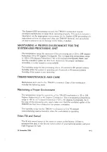
Page 75: ...o 80 percent relative humidity while the system is operating and 5 percent to 95 percent relative humidity if the system is not operating TM6OOO MAINTENANCE AND CARE Maintenance and care for the TM600 is rrinimal Care t rf the workstation includes the following items Maintaining a Proper Environment The temperature range for operation of the l M6 100 workstation is 32 to 104 degrees Fahrerrheit 0 ...

Page 76: ...tions Prevent loss of data or damage to floppy diskettes by storing them in a protected location having the following requirements o No direct sunlight o Temperature range from 50 to 125 degrees lrahar znheit 0 to 40 degreers Centigrade or as stated on the diskette which may vary from oae manufacturer to another e Relative humiclitv range from 8 to 80 percenl nonr ondensing No sources of magnetiza...

Page 77: ... 1 TM6000 Workstation Specifications A 2 Tables Dimensions and Weight of the 6300 processing Unit A 1 Power Requirements for the 6300 Processing Unit A 1 Environmental Specifications for the 6300 Processing Unit A 2 TM6000 Workstation Specifications A 2 A1 4 2 A 3 A4 15 November 1984 A i ii ...

Page 78: ......

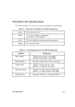
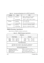
Page 79: ...g rear 2 inch standoff Weight 60 pounds 27 5 kilos Table A 2 Power Requirements for the 6300 Processing Unit Condition Requirement Input Voltage 110VAC Nominal 85 to 130V RMS 220VAC Nominal 200 to 260V RMS Input Frequency 50 60 Hz Nominal 47 to 63 Hz continuous Surge Current 115VAC 20 Amps for two cycles 220VAC 10 Amps for two cycles Operating Current 115VAC 2 6 Amps maximum 230 Watts 220VAC 1 3 A...

Page 80: ...A 4 lists the TM6000 workstation specifications Table A4 TM6000 Workstation Specifications Dimensions Video Display Keyboard Width 12 4 in 31 6 cm Height 11 9 in 30 2 cm Depth 11 6 in 29 5 cm Width 18 0 in 45 cm Heiglrt 1 2 in 3 ll cm Deptlr 7 9 in 19 cm Power Requirements 115 VAC at 47 220 Y AC at 47 to to 63 Hz I 63 Hz 5 amp domestic requirements amp foreign requirements Environmental Specifical...

Page 81: ... Unit Connectors B 1 TM6000 Workstation Connectors B 2 Illushations B 1 Rear View of the System 5300 Processing Unit B 1 B 2 TM6000 Workstation Keyboard Connectors B 2 B 3 TM6000 Workstation Rear View B 3 84 Power Module Connectors and Switch 84 15 November 1984 B i ii ...

Page 82: ......

Page 83: ...ms with other definiti cns in this section see the glossary at the end of this manual THE PROCESSING UNIT CONNECTORS The various connectors for the System 6300 processing unit are located on the rear of the unit where the power cord connector is located See Figure B 1 uo oN oFF SWITCH POWER CORD CONNECTOR Figure B 1 15 November 1984 STATUS INDICATORS LEDs CLUSTER PARALLEL PRINTER CHANNEL 1 CHANNEL...

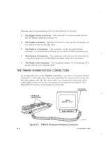
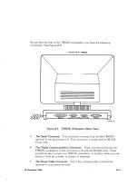
Page 84: ...al to the proces sing unit An R5232 Cross cable makes this connection The Power ord Connector This connector plr rgs in the processing unit s power cord to your electrical outlet THE TM6OOO WORKSTATION CONNECTORS As you face the frorrt of the TM6000 workstatiorl yoLr have a connector labeled keyboard on the right side of the base assembly that connects the keyboard to the video dlsplay unit with t...

Page 85: ...an RS 232 Cross cable o The Cluster Communications Connectors These connectors connect the TM6000 workstation to the processing unit with the RS 422 cable These connectors also connect one TM6000 workstation to another when you are trying to hook up a series or cluster of terminals o The Power Cable Connector This is the connector that connects the terminal to your power module REAR VIEW TMGOOO o ...

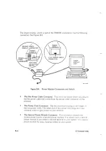
Page 86: ...ctor Use this connactor to plug in tlre longer rf the two powet cords The other end of this por ver cord plugs intc y our electrical outlet to give power to your terminal The Second l ower Module Connector This connector conne ts the shorter power c ord to a second power module Yrtu would neeC a secc rd power modulel if you added a second termiral to your system ou neer l a power moduler for every...

Page 87: ...ctors are sockets that hook up a cord or cable to make a connection generally between two or more units Cursor A cursor is the blinking marker on the video display screen that indicates your position on the screen It shows where you stopped writing and where you will start writing Diskette A diskette also called a floppy looks like a small music record in a dust jacket Part of the procedure to loa...

Page 88: ... this manual I Reference Manual I Introduction to thtr Subject I In a Class f Self Study I Introduction to ther System f Other Help us help you Please take the time to complete this form and send it to us If you do you may see some of your own contributions in the next manual you obtain from us MOTOBOLA INC 10700 North De Anza Blvd Cupertino CA 95014 Attention CSO Publications lt S 42 8G3 Please i...

Page 89: ...87601 1994 Sysiem 6300 äarciware lnstallation and User s Guide a i l i I i I i ...

Reviews: