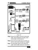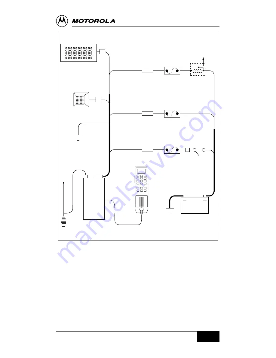
Figure 26
Step 5
Connect the D-type connector on the power
cable, and the modulator connector on the
control cable, to the transceiver.
Step 6
Check the power cable fuses and make sure
that the correct sizes and types are supplied.
Step 7
The green/black ignition sense lead of the
power cable should normally be connected to
To Lights,
Horn, etc.
2 Ampere
Blue Crimp
Connector
(not supplied)
AUX Alert
Yellow/
Black
Speaker
Digital
Hands-Free
Microphone
10 Ampere
Blue Crimp
Connector
Black
4 Ampere
Blue Crimp
Connector
Ignition
Sense
Green/
Black
Antenna
Transceiver
Control Cable
Handset
Chassis
Ground
Chassis
Ground
Battery
Power Cable
Relay
(500 mA max.
coil rating)
Red
Ignition
Switch
In-Line
Splice
Installation Manual
37
Summary of Contents for T5ZX1
Page 2: ...Cellular Mobile and Attache Accessory Installation Manual ...
Page 8: ...Figure 4a Figure 4b Installation Manual 5 ...
Page 56: ......
Page 57: ......

