background image

30


August 20, 2003


6809471A67-O

Disassembly

 V150

Removing the Rear Housing


1.

Remove the battery cover, battery, antenna, and light guide as described in 
the procedures.

2.

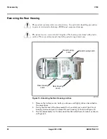
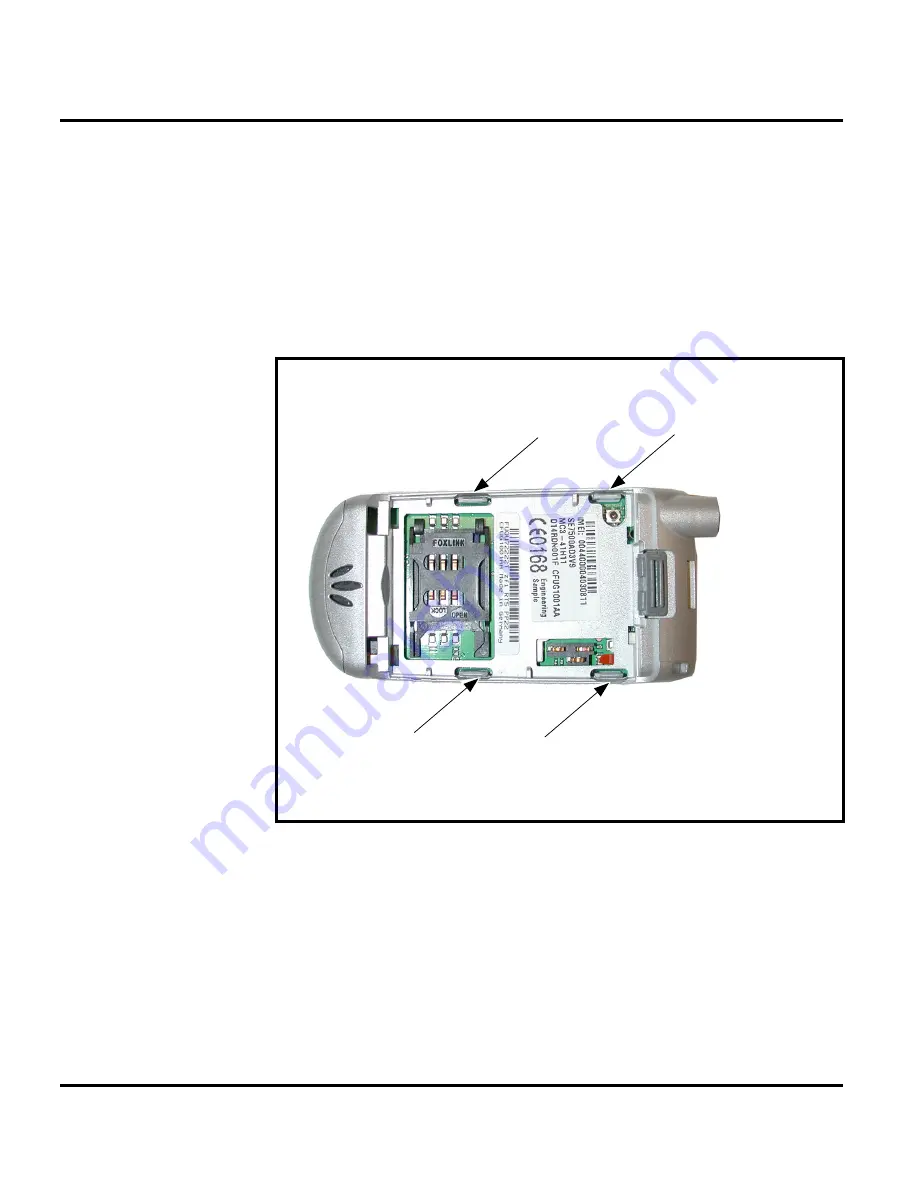
Using the flat end of the disassembly tool, carefully pry each of the 4 front 
housing latches inward to release the rear housing as shown in Figure 10.

3.

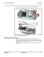
Use the disassembly tool to disconnect the flex cable from its socket as shown 
in Figure 11.

G

This product contains static-sensitive devices. Use anti-static handling procedures 
to prevent electrostatic discharge (ESD) and component damage.

G

The phone has no screws to hold it together. The housing is fastened with plastic 
catches. These are delicate and should be parted using utmost care.


031732o

Figure 10. Unlocking the Rear Housing Latches

Rear Housing Latch

Rear Housing 

Latch

Rear Housing

Latch

Rear Housing

Latch

Summary of Contents for V150

Page 1: ...Level 1 and 2 Service Manual V150 Dual Band Wireless Telephone GSM 900 DCS 1800MHz with GPRS ...

Page 2: ......

Page 3: ...25 Removing the SIM Card 26 Replacing the SIM Card 26 Removing and Replacing the Antenna 27 Removing and Replacing the Light Guide 28 Removing the Rear Housing 30 Replacing the Rear Housing 31 Removing the Transceiver Board 32 Replacing the Transceiver Board 33 Removing and Replacing the Microphone and Microphone Grommet 34 Removing and Replacing the Keypad PCB 35 Removing and Replacing the Keypad...

Page 4: ...4 August 20 2003 V150 ...

Page 5: ...duct names included in V150 telephones are listed on the front cover Product names are subject to change without notice Some product names as well as some frequency bands are available only in certain markets Product Changes When electrical mechanical or production changes are incorporated into Motorola products a revision letter is assigned to the chassis or kit affected for example A B or C and ...

Page 6: ...oper installation operation and maintenance of V150 Series telephones Refer questions about this manual to the nearest Customer Service Manager Audience This document aids service personnel in testing and repairing V150 telephones Service personnel should be familiar with electronic assembly testing and troubleshooting methods and with the operation and use of associated test equipment Use of this...

Page 7: ...mponent repairs Customer Support Customer support is available through dedicated Call Centers and in country help desks Product Service training should be arranged through the local Motorola Support Center Parts Replacement When ordering replacement parts or equipment include the Motorola part number and description used in the service manual or supplement When ordering crystals or channel element...

Page 8: ... your TTY call 800 793 7834 Accessories and Aftermarket Division AAD Replacement parts test equipment and manuals can be ordered from AAD To order spare parts in the EMEA region call 44 131 479 1274 To order spare parts in Asia call 65 648 62995 U S A Outside U S A Phone 800 422 4210 Phone 847 538 8023 FAX 800 622 6210 FAX 847 576 3023 ...

Page 9: ...e w Slim LI Battery 69 cc 4 1 cubic inches Weight 106 gm 3 74 oz with cell Temperature Range 10 C to 55 C 15 F to 130 F Battery Life 600 mAh Li Ion Battery Talk time up to 300 minutes Standby time up to 300 hours All talk and standby times are approximate and depend on network configuration signal strength and features selected Standby times are quoted as a range from DRX 2 to DRX 9 Talk times are...

Page 10: ...6809471A67 O Specifications V150 Bit Rate 13 0 kbps Frame Duration 20 ms Block Length 260 bits Classes Class 1 bits 182 bits Class 2 bits 78 bits Bit Rate with FEC Encoding 22 8 kbps Speech Coding Function Specification ...

Page 11: ...ources are not consumed during periods when a user is not actually sending or receiving data The telephones are made of polycarbonate plastic with a metal enclosure The display and speaker as well as the 18 key keypad transceiver printed circuit board PCB microphone charger and headphone connectors and power button are contained within the flip phone form factor housing The 600 mAh Lithium Ion Li ...

Page 12: ...vation The voice dialing feature allows the user to recall pre programmed voice numbers simply by pressing the Voice Ok key and speaking the desired voice tag Up to 10 voice tags can be stored Wireless Access Protocol WAP 1 2 Compliancy In the WAP environment access to the Internet is initiated in wireless markup language WML which is derived from hypertext markup language HTML The request is pass...

Page 13: ...ffer their customers from the occasional user who requests sports news and traffic alerts to a high call time business user who receives stock alerts and checks flight times Operators can now create their own value added services menu quickly and easily in the phone The customized menu will appear as the first menu and may be updated over the air with new services when customers request them Netwo...

Page 14: ...d icon and graphical based user interface The phone also features a user definable Quick Access menu that is accessed by holding down the MENU key See Figure 3 for details of theV150 menu structure A 4 way navigation key allows you to move easily through menus Figure 1 Telephone Controls Indicators and I O Earpiece Headset Jack Insert headset accessory for hands free use Display Microphone Accesso...

Page 15: ...ppears when the phone uses another network system outside the user s home network When leaving the home network area the phone roams or seeks another network 4 Message Waiting Indicator4 appears when the phone receives a text mes sage 5 Voice Message Waiting Indicator4 icon indicates when the phone receives a voicemail message 6 Battery Level Indicator shows the amount of charge left in the batter...

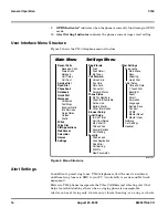
Page 16: ...e Main Menu Recent Calls Received Calls Dialed Calls Notepad Call Times Call Cost Service Dial Fixed Dial Phonebook Datebook Quick Dial Messages Voicemail Text Msgs Browser Alerts Info Services Quick Notes Outbox Drafts 2Click Voice Dial SIM Applications WebAccess Calculator Games Settings Settings Menu Ring Vibrate Alert Alert Detail My Tones Call Forward Voice Calls Fax Calls Data Calls Cancel A...

Page 17: ...k partially entered phone book entries or outgoing messages for example is lost E All batteries can cause property damage and or bodily injury such as burns if a conductive material such as jewelry keys or beaded chains touch exposed terminals The conductive material may complete an electrical circuit short circuit and become quite hot Exercise care in handling any charged battery particularly whe...

Page 18: ...acters A Motorola Penang J ESG Chihuahua S T D I Scotland B T D I Mexico K T D I Romeoville T T D I Downers Grove C Motorola China L Motorola Lawrenceville U T D I Hungary D T D I Shanghai China M TDI Malaysia V E ESG Evadin Brazil N TDI Manau Brazil W ESG Sung Woo F ESG Propower Korea O X ESG Foxlink China G P Intesys Arizona Y P K G E T Systems Korea H Motorola Harvard Q Z I Motorola lreland R C...

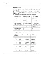
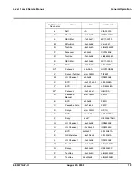
Page 19: ... Chemical 6x30x48 ICP633048 3X BYD 5 4x30 1x48 2 LP053048A 3Y BYD 6x34x50 LPO53048A 3Z Panasonic 6 2x35 2x16 HF6OSS 4A Peacebay Manual 6mm NiMH F6MG 4B BYD 4x30x48 F6MG 4C Peacebay Auto 6 4x16 34 F6MP 4D Sanyo 6mm NiMH HFC1U 4E BYD 8x3 x47 5 LP083448SH 4F Sony 34x67 UP423467A4H 4G LG Chemical 8 6x34x48 ICP863448 4H LG Chemical 6 3x 34x50 ICP633450 4J BYD 4x30x41 LP043O41A 4K GS Melcotec 4 6x29 5x4...

Page 20: ... date code A1V90311JCCC position 1 A Motorola Penang t Backend Pack position 2 3 1V Panasonic AAA HHR55B2 position 4 5 6 903 cell date code from manufacturer position 7 8 11 TBD by supplier Example Line one of the first shift position 9 J 1999 Year of battery pack manufacture position 10 11 CC week twenty two backend pack position 12 C Motorola China Frontend Core Pack position 13 14 15 placeholde...

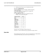
Page 21: ...a sequence number 9 Embedded battery packs use a 6 character date code Position 1 is the manufacturing site Position 2 and 3 is cell code and vendor See step 2 Position 4 5 and 6 is cell date code year and week See steps 5 and 6 Operation For detailed operating instructions refer to the appropriate User Guide listed in the Related Publications section toward the end of this manual Manufacturing Si...

Page 22: ...22 August 20 2003 6809471A67 O General Operation V150 ...

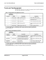
Page 23: ...00 2 To order in EMEA region contact Motorola GmbH International Service Engineering Group web site http 212 112 205 178 Table 2 General Test Equipment and Tools Motorola Model Number Americas1 EMEA2 Description Application 0180386A82 0180386A82 Antistatic Mat Kit includes 66 80387A95 antistatic mat 66 80334B36 ground cord and 42 80385A59 wrist band Provides protection from damage to device caused...

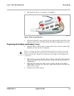
Page 24: ...e the phone is turned off 2 Slide the battery cover release in the direction of the arrow see Figure 4 G Many of the integrated devices used in this equipment are vulnerable to damage from electrostatic discharge ESD Ensure adequate static protection is in place when handling shipping and servicing the internal components of this equipment G Avoid stressing the plastic in any way to avoid damage t...

Page 25: ...prongs on top of the battery with the receptacles molded into the housing then press the bottom end of the battery securely into the battery compartment 3 Align the bottom end of the battery cover with the notches in the battery compartment and rotate the top of the compartment downward towards the battery cover release 4 Snap the cover firmly in place 001075 O Figure 5 Removing the Battery E Ther...

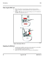
Page 26: ...SIM holder upward as shown in Figure 6 arrow B and slide out the SIM card as shown by arrow C Replacing the SIM Card 1 Carefully insert the SIM card into the slot in the holder Be sure the SIM is correctly positioned to contact the socket when closed 2 Close the holder and slide to lock in place 3 Replace the battery and battery door as described in the procedures 001086 O Figure 6 Removing the SI...

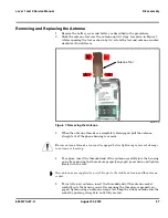
Page 27: ...nsert the threaded end of the antenna carefully into the housing and after ensuring the threads are properly engaged press down and tighten firmly with the tool 5 To install a new antenna insert the threaded end of the antenna socket carefully into the housing and after ensuring the threads are properly en gaged tighten using an antenna torque tool Snap the stubby antenna into the socket by pushin...

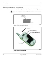
Page 28: ...enna as described in the procedures G Use extreme care when removing the light guide to prevent damage to the transceiver board ZIF connector 010089 O Figure 8 LED Removal Tool Modification 001084 O Figure 9 Removing the Light Guide Light Guide Removal Tool Light Guide Removal tool Light Guide Access Hole Light Guide Rear Housing ...

Page 29: ...e mark on the tool 5 If resistance is felt at a depth of 9 6 mm or less as indicated by the depth mark on the tool the tool has contacted the edge of the transceiver board ZIF connector Raise the tool slightly to clear the connector 6 Resistance felt at a depth greater than 9 6 mm means the tool is clear of the ZIF connector and has properly contacted the light guide 7 When the tool is in contact ...

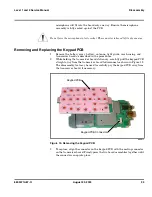
Page 30: ... 3 Use the disassembly tool to disconnect the flex cable from its socket as shown in Figure 11 G This product contains static sensitive devices Use anti static handling procedures to prevent electrostatic discharge ESD and component damage G The phone has no screws to hold it together The housing is fastened with plastic catches These are delicate and should be parted using utmost care 031732o Fig...

Page 31: ...ket on the transceiver board 2 Align the 4 front housing catches with the matching slots in the rear housing then firmly press the rear housing to the front housing until the catches engage and the housings are properly assembled 3 Replace the light guide antenna battery and battery cover as described in the procedures 031753o Figure 11 Removing the Rear Housing Rear Housing Rear Housing Flex Cabl...

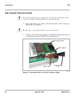
Page 32: ...refully lift the ZIF connector latch on the transceiver board to unlock the flex see Figure 12 G This product contains static sensitive devices Use anti static handling procedures to prevent electrostatic discharge ESD and component damage G The flex cable is easily damaged Exercise care when handling 031799o Figure 12 Disconnecting the Flex from the Transceiver Board Flex Cable Disassembly Tool Z...

Page 33: ... 1 Insert the transceiver board into the front housing with the ZIF connector on top Ensure the keypad PCB is properly aligned with the keypad 2 Insert the flex squarely into the ZIF connector on the transceiver board and close the connector latch until it locks into position 3 Replace the rear housing light guide antenna battery and battery cover as described in the procedures 031733o Figure 13 R...

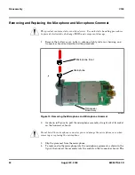
Page 34: ...et from the microphone 4 To replace slip the microphone into the microphone grommet as shown in the figure then insert the assembly into the socket on the transceiver board The G This product contains static sensitive devices Use anti static handling procedures to prevent electrostatic discharge ESD and component damage 031802o Figure 14 Removing the Microphone and Microphone Grommet G Do not bend...

Page 35: ...rd stationary carefully pull the keypad PCB straight away from the transceiver board to disconnect as shown in Figure 15 The disassembly tool may be used to carefully pry the keypad PCB away from the transceiver board if necessary 3 To replace align the connector on the keypad PCB with the mating connector on the transceiver board Firmly press the two board assemblies together until the connectors...

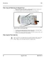
Page 36: ...ont housing ensuring the keys align properly with the openings in the front housing 4 Replace the transceiver board rear housing light guide antenna battery and battery cover as described in the procedures Removing the Flip Assembly 031800o Figure 16 Removing the Keypad Keys G There are no Level 1 or 2 replaceable parts in the V150 telephone flip assembly The flip assembly is not removable from th...

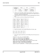
Page 37: ...ptions are required to be transferred to the replacement unit Master Transfer Used when the faulty unit will not power up and the trans fer is used to configure the replacement board to a set standard Listed below are the procedures to set up a master transfer card and to perform each method of transfer Normal Transfer 1 Remove the battery cover and battery from the customer s phone as described i...

Page 38: ...n 6 Using the keypad buttons type 024 to copy the personality from the unit to the transfer SIM card Please wait displays on the screen 7 When Clone displays on the screen the transfer is complete and the Master Transfer card is created Master Transfer 1 Remove the battery cover and battery from the replacement unit as described in the procedures 2 If required remove the SIM card from the replacem...

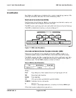
Page 39: ...red within the unit s memory The IMEI uniquely identifies an individual mobile station and thereby provides a means for controlling access to GSM networks based on mobile station types or individual units The full IMEI structure is listed in Table 3 Where TAC Type Allocation Code formerly known as Type Approval Code NN Reporting body identifier XXXX Type Identifier YY YY is set to 00 from 01 01 20...

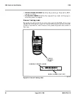
Page 40: ... Tracking Label The number recorded on the Picasso label when used with the MSN allows precise identification of the device s origin By tracking field failures back to the site shift and line of manufacture failure trends can be quickly diagnosed and corrected at the source 001157 O Figure 18 Picasso Tracking Label S U G 4039 A C15 Mms D 505600368 D505600368 6050 MADE IN IRELAND PICASSO TRACKING L...

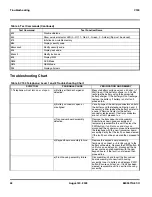
Page 41: ...ttery and battery cover as described in the procedures 6 Press to turn the phone ON Press and hold the button for approximately 3 seconds until TEST displays on the screen The phone may now be issued test commands listed in Table 4 Manual Test Mode Commands Table 4 Test Commands Test Command Test Function Name Press and hold for 2 seconds Enter manual test mode 01 Exit manual test mode 07x Mute RX...

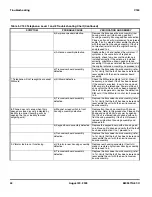
Page 42: ...ce the battery or refer to a Level 3 Service Center for the battery connector replacement If battery connectors are not at fault proceed to c c Transceiver board assembly defective Remove the transceiver board assembly Substitute a known good assembly and temporarily reassemble the unit Depress the PWR button if unit turns on and stays on disconnect the dc power source and reassemble the telephone...

Page 43: ...been cleared and reassemble the unit with the new transceiver board assembly 4 Incoming call alert transducer audio distorted or volume is too low a Faulty transceiver board assembly Replace the transceiver board assembly refer to 1c Verify that the fault has been cleared and reassemble the unit with the new transceiver board assembly 5 Telephone transmit audio is weak usually indicated by called ...

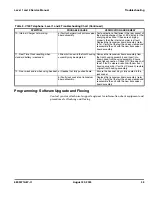
Page 44: ...sceiver board assembly defective Replace the transceiver board assembly refer to 1c Verify that the fault has been cleared and reassemble the unit with the new transceiver board assembly 8 Phone does not sense when flip is opened or closed usually indicated by inability to answer incoming calls by opening the flip or inability to make outgoing calls a Magnet or reed switch in front housing assembl...

Page 45: ...Time Clock resetting when standard battery is removed Lithium button cell in the front housing assembly may be depleted Remove the transceiver board assembly from the front housing assembly and insert into known good front housing assembly Ensure good flex connection Check RTC time does not reset If fault is cleared rebuild with new front housing assembly If fault is still present restore original...

Page 46: ...003 6809471A67 O Part Number Charts V150 Part Number Charts The following charts are provided as a reference for the parts associated with V150 telephones Exploded View Diagram 031741o Figure 19 Exploded View Diagram ...

Page 47: ...hamber foam 7 0185779K19 Flip rear housing 16 6185635H04 Charger light pipe 8 CFLG1001 Keypad PCB Dome array Assembly 17 0103555B01 Power flex 9 CFLG10002 Main PCB assembly 5009135L07 microphone 0585699J01 microphone grommet Notes 1 Order next higher assembly 2 Not available as spares in EMEA Service markets E There is a danger of explosion if the Lithium Ion battery pack is replaced incorrectly R...

Page 48: ... Ion 500 mAh SNN5435 Charger Desktop SHN7498 Power Adapter SPN4604 Adapter Plug UK SYN7455 Adapter Plug Europe SYN7456 Adapter Plug Australia New Zealand SYN8127 Adapter Plug India SYN7461 Vehicle Power Adapter SYN4241 Smart CELLect 2000 Cable PCC7000 Personal Handsfree System SYN8390 Leather Holster SYN8089 V150 Dual Band Mobile Telephone User s Guide English ...

Page 49: ...ecognition 12 Wireless Access Protocol WAP 12 flex disconnecting from transceiver board 32 flip assembly removing and replacing 36 H headset jack 14 I identification 39 international mobile station equipment identity 39 mechanical serial number 39 Picasso tracking label 40 product 5 IMEI 39 Introduction 5 K key end 14 left soft key 14 menu 14 right soft key 14 scroll 14 send 14 keypad keys removin...

Page 50: ...ery 17 24 battery door 24 flex 32 flip assembly 36 keypad keys 36 keypad PCB 35 light guide 28 microphone 34 microphone grommet 34 rear housing 30 SIM card 26 transceiver board 32 replacement parts ordering 7 replacing antenna 27 battery 25 battery door 25 flip assembly 36 keypad keys 36 keypad PCB 35 light guide 28 microphone 34 microphone grommet 34 rear housing 31 SIM card 26 transceiver board ...

Page 51: ... Manual customer 7 product 7 T test equipment 23 text entry 13 tools 23 transceiver board removing 32 replacing 33 troubleshooting 41 manual test mode 41 manual test mode commands 41 V voice recognition 12 W WAP Wireless Access Protocol 12 warranty service 7 ...

Page 52: ...Index 4 February 13 2001 6809471A67 O V150 ...

Page 53: ......

Page 54: ...erein are trademarks of Motorola Inc Reg U S Pat Tm Off All other product or service names are the property of their respective owners 2003 Motorola Inc All rights reserved Personal Communications Sector 789 International Parkway Sunrise FL 33322 6220 6809471A67 6809471A67 O ...
Reviews: