


CMOS Clear Header (JP1)
http://www.motorola.com/computer/literature
1-5
1
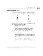
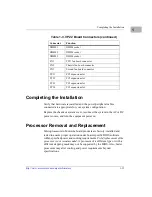
CMOS Clear Header (JP1)
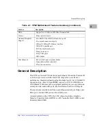
The CMOS Clear function is controlled by a 3-pin header. Putting a jumper
on JP1 pins 1-2 is the normal setting and putting a jumper on JP1 pins 2-3
clears the CMOS. The default setting is with a jumper installed on pins 1-2.
If you encounter any of the following, you can reconfigure the system with
the default values stored in the ROM BIOS.
❏
CMOS data becomes corrupted
❏
You forgot the supervisor or user password
❏
You are unable to boot-up the computer system because the
processor’s clock/ratio was incorrectly set in the BIOS
To load the default values stored in the ROM BIOS, follow the steps
below:
1. Power off the system.
2. Remove jumper from JP1 pins 1-2 and put on JP1 pins 2-3. Wait
for a few seconds and set JP1 back to its default setting, pins 1-2.
3. Power on the system.
4. After powering on the system, press <Del> to enter the BIOS
setup utility. Refer to the VP22 microATX Motherboard BIOS and
Programmer’s Reference Guide for more information.
JP1
CMOS Clear
3
2
1
JP1
Normal
3
2
1
(factory configuration)
(factory configuration)


