


1-8
Computer Group Literature Center Web Site
Hardware Preparation and Installation
1
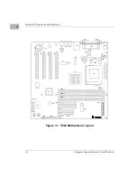
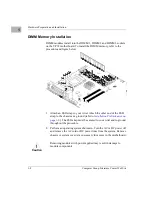
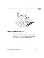
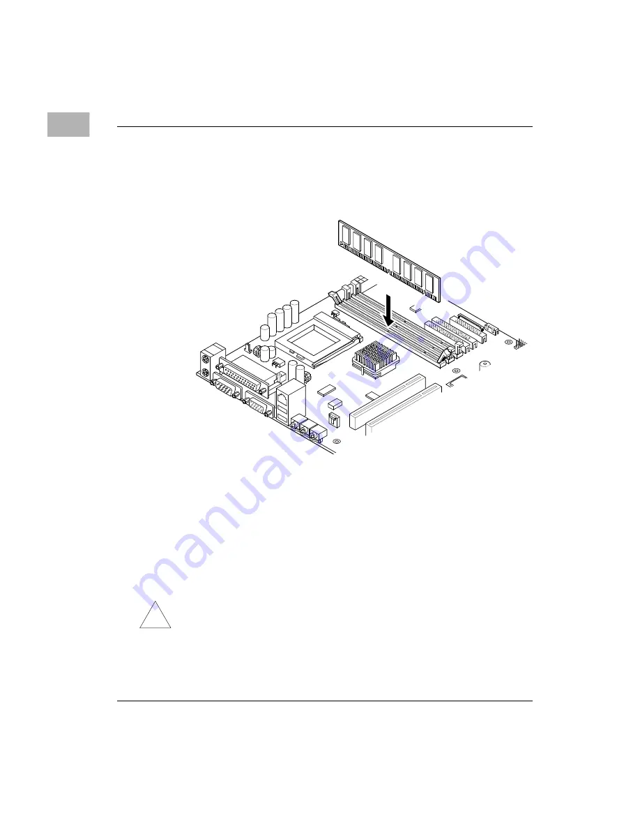
DIMM Memory Installation
DIMM modules install into the DIMM 1, DIMM 2 and DIMM 3 sockets
on the VP22 motherboard. To install the DIMM memory, refer to the
procedure and figure below.
1. Attach an ESD strap to your wrist. Attach the other end of the ESD
strap to the chassis as a ground (refer to
). The ESD strap must be secured to your wrist and to ground
throughout the procedure.
2. Perform an operating system shutdown. Turn the AC or DC power off
and remove the AC cord or DC power lines from the system. Remove
chassis or system cover(s) as necessary for access to the motherboard.
!
Caution
Caution
Removing modules with power applied may result in damage to
module components.


