


Completing the Installation
http://www.motorola.com/computer/literature
1-13
1
Completing the Installation
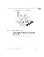
Verify that hardware is installed and the power/peripheral cables
connected are appropriate for your system configuration.
Replace the chassis or system cover, reconnect the system to the AC or DC
power source, and turn the equipment power on.
Processor Removal and Replacement
Microprocessors in Motorola board products are factory-installed and
tested to ensure proper operation under board-specific BIOS software
within specified power and cooling requirements. Field replacement of the
processor is not recommended. A processor of a different type or with a
different stepping mask may not be supported by the BIOS. Also, faster
processors may alter cooling and power requirements beyond
specifications.
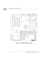
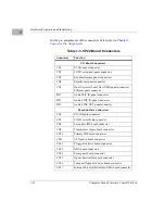
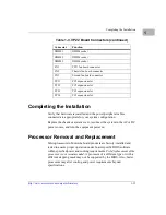
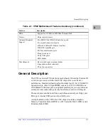
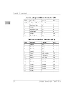
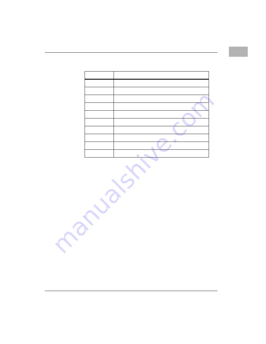
DIMM 1
DIMM socket
DIMM 2
DIMM socket
DIMM 3
DIMM socket
FN1
CPU fan board connector
FN2
Chassis fan board connector
FN3
Second fan board connector
PCI 1
PCI expansion slot
PCI 2
PCI expansion slot
PCI 3
PCI expansion slot
PCI 4
PCI expansion slot
Table 1-3. VP22 Board Connectors (continued)
Connector
Function


