


Connector Pin Assignments
http://www.motorola.com/computer/literature
3-3
3
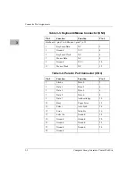
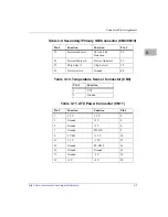
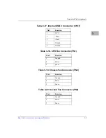
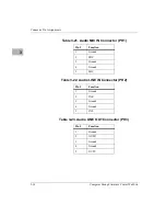
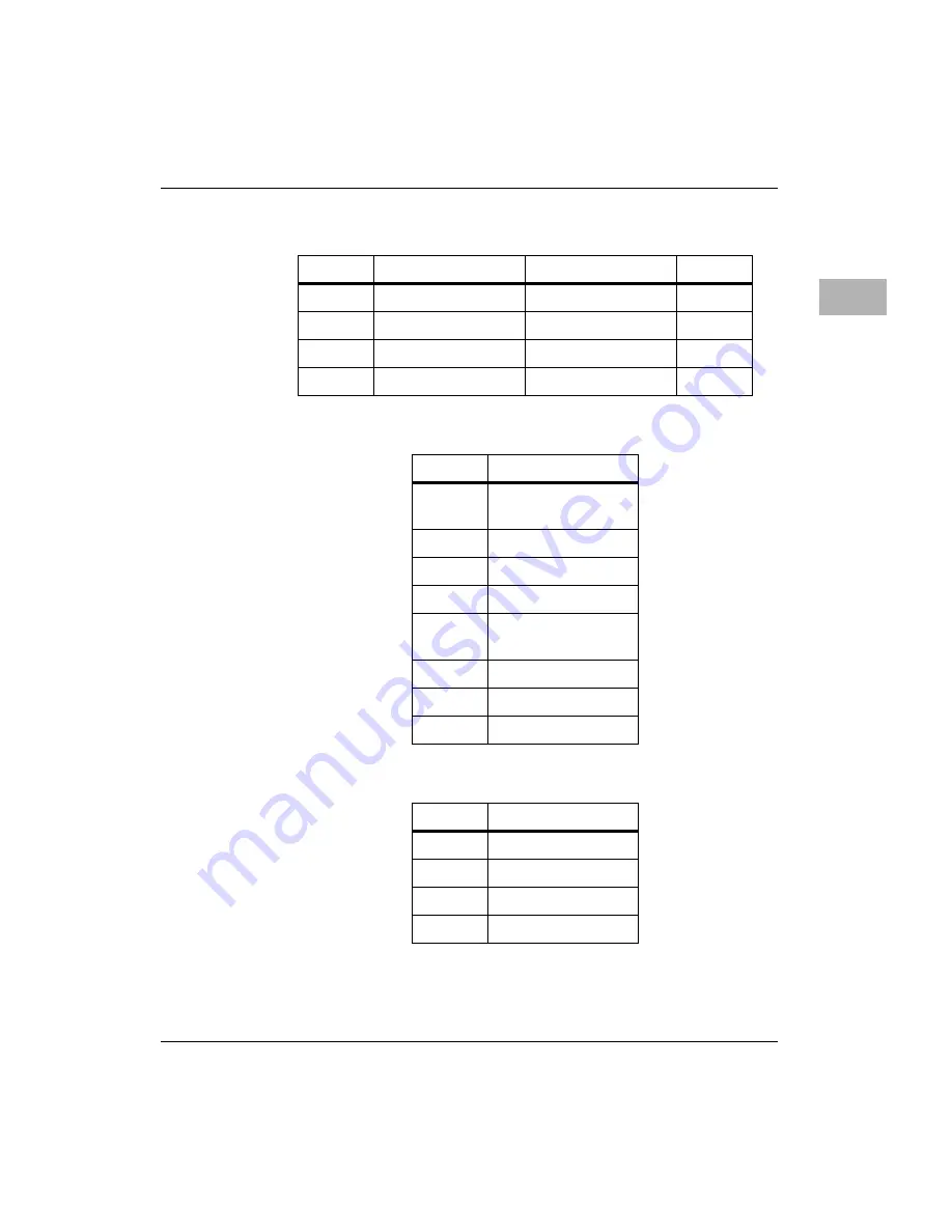
Table 3-5. Ethernet Connector (CN5)
Pin #
Function
Function
Pin #
1
Transmit Data (+)
Transmit Data (–)
2
3
Receive Data (+)
Termination
4
5
Termination
Receive Data (–)
6
7
Termination
Termination
8
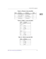
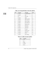
Table 3-6. USB 0, 1 Connector (CN5)
Pin #
Function
L1
(lower)
VCC
L2
–Data
L3
+Data
L4
Ground
U1
(upper)
VCC
U2
–Data
U3
+Data
U4
Ground
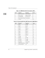
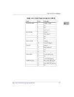
Table 3-7. CD-IN Connector (CN6)
Pin #
Function
1
Left
2
Ground
3
Ground
4
Right


