

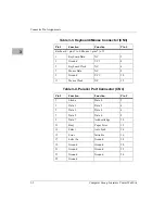
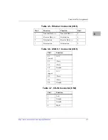
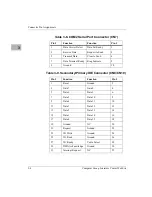
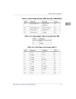


Connector Pin Assignments
http://www.motorola.com/computer/literature
3-7
3
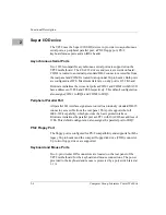
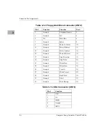
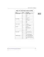
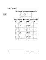
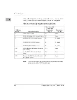
Table 3-14. Front Panel Connector (CN14)
Item
Pin #
Function
Chassis Speaker
1
Speaker signal
3
NC
5
NC
7
VCC (5 V)
Reset Button
2
Ground
4
Reset signal
6
NC
9
NC
Power Switch
8
Ground
10
Power-on signal
Keylock
11
Ground
13
Keyboard lock
12
NC
14
NC
Power LED
15
Power LED signal
17
NC
19
Power LED pull-up
Hard Disk LED
16
Hard Disk LED signal
18
Hard Disk LED pull-up
20
NC


