


ix
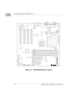
Figure 1-1. VP22 Motherboard Layout ................................................................... 1-4
Figure 2-1. VP22 Block Diagram ........................................................................... 2-1
Figure B-1. Thermally Significant Components—Primary Side ............................B-3
Figure B-2. Mounting a Thermocouple Under a Heatsink .....................................B-5
Figure B-3. Measuring Local Air Temperature .......................................................B-6
List of Figures


