Chapter 2: Hardware Interface Description
May 31, 2008
Module Hardware Description
25
Audio Interface
W24 incorporates Audio interface intended to support G24 Audio interface, in stacked
configuration. The interface consists of the following pins (see
Table 2-8
for analog audio and
Table 2-9
for digital audio):
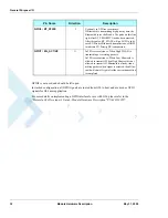
The above signals are routed from 70-pin host connector to G24 70-pin connector via W24. They
are not internally connected to W24 circuits. If the W24 will be used as stand alone only, the
above pins should be left open.
For more details on implementing a Audio interface for use with G24, please refer to the
"Motorola G24 Developer's Guide - Module Hardware Description" PN 6889192V27
Table 2-8: Analog Audio Interface Signals
Pin #
Pin Name
Description
55
HDST_INT_N
Headset detect interrupt
57
HDST_MIC
Headset microphone input
59
AGND
Audio ground
61
MIC
Microphone input
63
ALRT_N
Alert speaker inverted
65
ALRT_P
Alert speaker
67
SPKR_N
Speaker inverted
69
SPKR_P
Speaker
Table 2-9: Digital Audio Interface Signals
Pin #
Pin Name
Description
18
PCM_DIN
Digital audio receive
20
PCM_DOUT
Digital audio transmit
22
PCM_CLK
Digital audio clock
24
PCM_FS
Digital audio clock
Summary of Contents for W24
Page 4: ......
Page 8: ...Table of Contents iv Module Hardware Description May 31 2008 ...
Page 28: ...Regulatory Approvals 6 Module Hardware Description May 31 2008 ...
Page 56: ...Antenna Interface 34 Module Hardware Description May 31 2008 ...
Page 84: ...Index W W Index 2 Module Hardware Description May 31 2008 ...
Page 85: ......


