Controls and Indicators Interface
30
Module Hardware Description
May 31, 2008
For more details on implementing a GPRS/EGPRS signal for use with G24, please refer to the
"Motorola G24 Developer's Guide - Module Hardware Description" PN 6889192V27
Transmission Indicator
This signal is routed from the 70-pin host connector to G24 70-pin connector via W24. It is not
internally connected to W24 circuits. If the W24 will be used as stand alone only, the signal pin
should be left open.
For more details on implementing a GPRS/EGPRS signal for use with G24, please refer to the
"Motorola G24 Developer's Guide - Module Hardware Description" PN 6889192V27
Wi-Fi LED Indicator
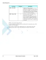
Wi-Fi LED Indicator is an output which indicates the Wi-Fi activity. WIFI_LED_LCD_RS signal
is mapped on the pin 60 of the 70-pin Host Connector.
Mode Select
This signal sets the W24 mode of operation. It should be left open for normal operation. If pulled
to ground at power up for 3s, it forces a module in boot mode.
Summary of Contents for W24
Page 4: ......
Page 8: ...Table of Contents iv Module Hardware Description May 31 2008 ...
Page 28: ...Regulatory Approvals 6 Module Hardware Description May 31 2008 ...
Page 56: ...Antenna Interface 34 Module Hardware Description May 31 2008 ...
Page 84: ...Index W W Index 2 Module Hardware Description May 31 2008 ...
Page 85: ......


